![[Previous]](../../../buttons/fprev.png)
![[Next]](../../../buttons/fnext.png)
DTC B1B54: Seat
Belt Buckle Switch (RH) Circuit (Ground Side) Shorted
DTC B1B55: Seat Belt Buckle
Switch (RH) Circuit (Power Supply Side) Shorted
DTC B1B56: Seat Belt Buckle Switch
(RH) Circuit Open
| caution |
If DTC B1B54, B1B55 or B1B56 are set in the SRS-ECU, always
diagnose the CAN main bus lines.
|
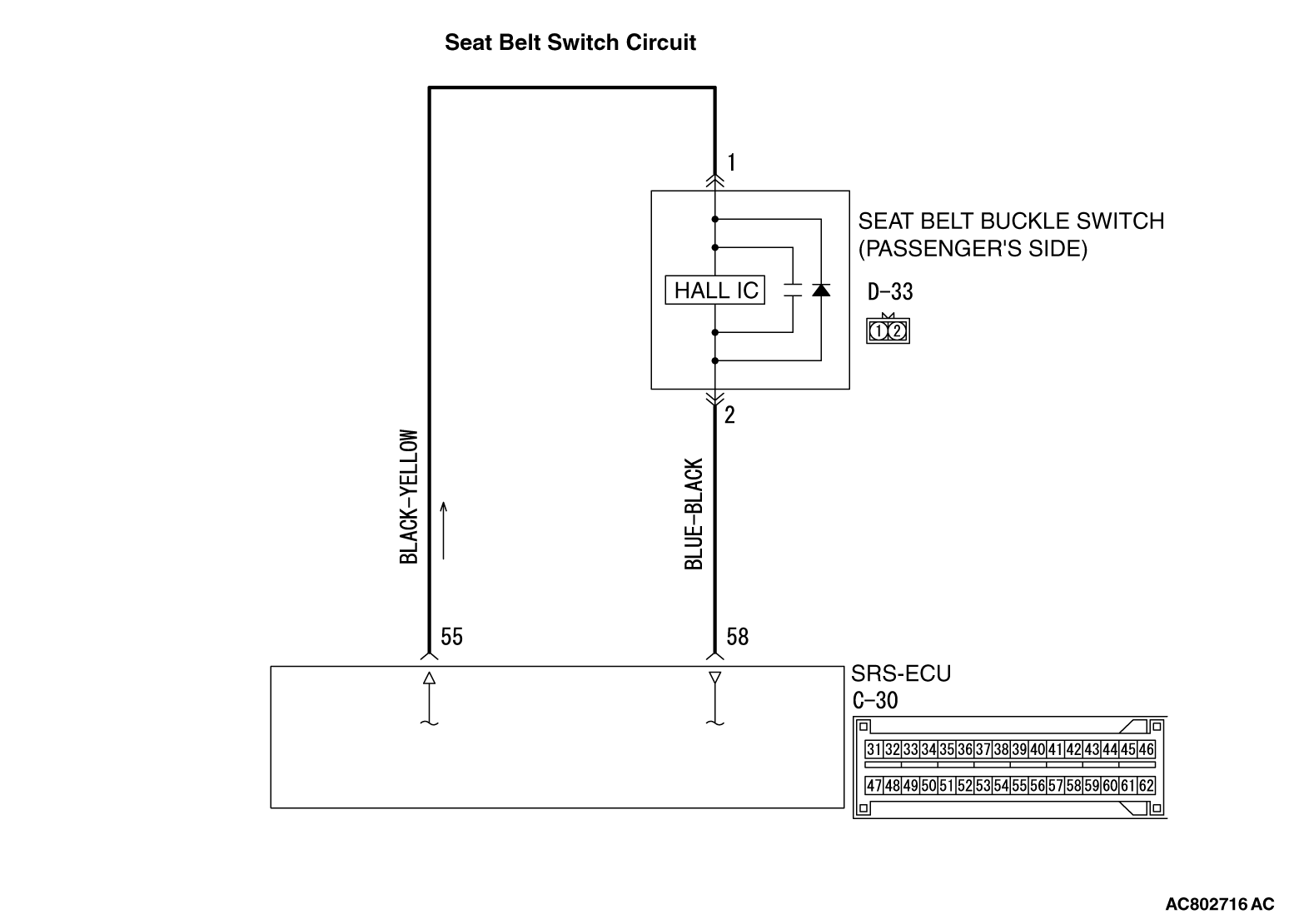
CIRCUIT OPERATION
The SRS-ECU determines whether the seat belt is fastened or not according to the connection location
of the seat belt buckle switch in the seat buckle.
DTC SET CONDITIONS
The DTC is set when the seat belt buckle switch output current is not within the specified range.
TROUBLESHOOTING HINTS
- Malfunction of the seat belt buckle switch
- Damaged wiring harnesses or connectors
- Malfunction of the SRS-ECU
|
|
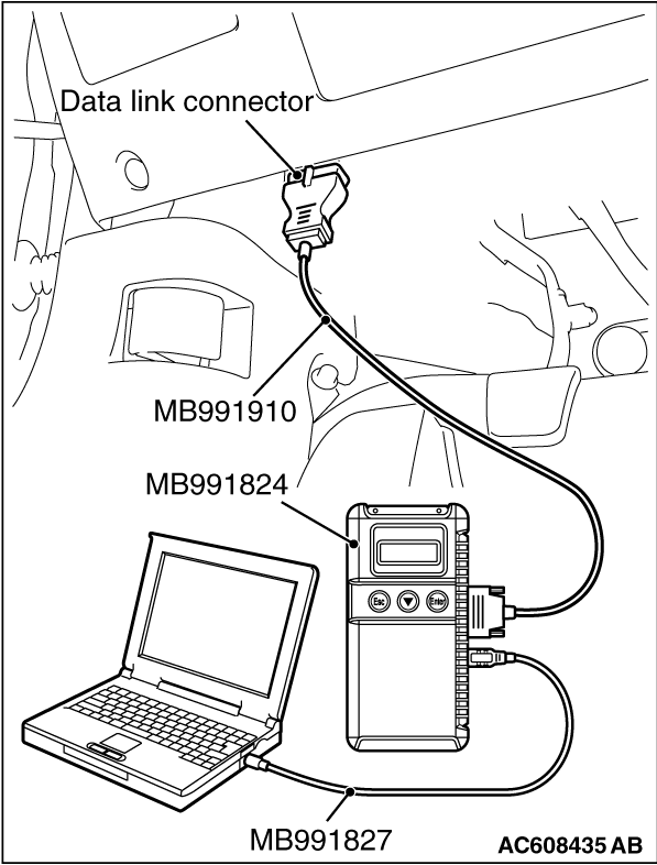
Required Special Tools:
- MB991222: Probe
- MB991958: Scan Tool (M.U.T.-III Sub Assembly)
- MB991824: Vehicle Communication Interface (V.C.I.)
- MB991827: M.U.T.-III USB Cable
- MB991910: M.U.T.-III Main Harness A (Vehicles with CAN communication system)
|
|
|
STEP 1. Using scan tool MB991958, diagnose the CAN bus
line.
|
|
(1)
| caution |
To prevent damage to scan tool MB991958, always turn the ignition switch to the "LOCK" (OFF)
position before connecting or disconnecting scan tool MB991958.
|
Connect scan tool MB991958. Refer to "How to connect the scan tool  ." ."
(2)Connect scan tool MB991958 to the data link connector.
(3)Turn the ignition switch to the "ON" position.
(4)Diagnose the CAN bus line.
(5)Turn the ignition switch to the "LOCK" (OFF) position.
Q.
Is the CAN bus line found to be normal?
 Go to Step 2. Go to Step 2.
 Repair the CAN bus line (Refer to GROUP 54C, Diagnosis ). Repair the CAN bus line (Refer to GROUP 54C, Diagnosis ).
|
|
|
STEP 2. Recheck for diagnostic trouble code.
|
|
|
Check again if the DTC is set.
|
|
|
(2)Turn the ignition switch to "ON" position.
|
|
|
(3)Check if the DTC is set.
|
|
|
(4)Turn the ignition switch to the "LOCK" (OFF) position.
|
|
|
Go to Step 3.
|
|
|
|
|
|
There is an intermittent malfunction such as poor engaged connector(s) or open
circuit (Refer to GROUP 00, How to Cope with Intermittent Malfunction ).
|
|
|
|
|
|
STEP 3. Check the harness short circuit between seat belt buckle switch
(passenger’s side) connector D-33 and the SRS-ECU connector C-30.
|
|
|
(1)Disconnect the negative battery terminal.
|
|
|
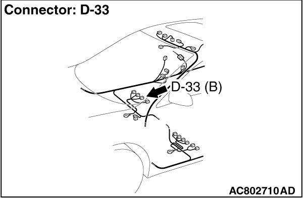
(2)Disconnect the seat belt buckle switch (passenger’s side) connector D-33.
|
|
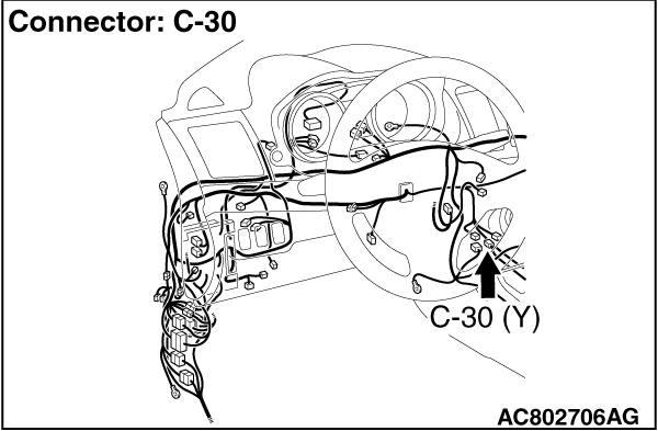
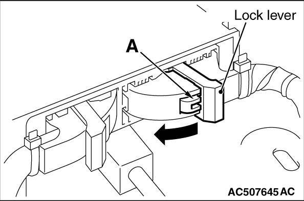
(3)While pushing the part "A" indicated in the figure of the harness side connector, turn
the lock lever to the direction of the arrow to release the lock lever, and disconnect the C-30
SRS-ECU connector.
|
|
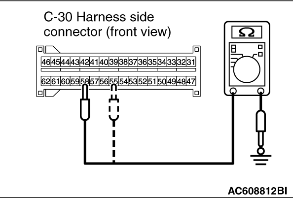
(4)Measure the resistance between terminal 55, 58 and body ground (No. B1B54 only).
It should be an open circuit.
(5)Connect the negative battery terminal.
(6)Ignition switch: ON.
|
|
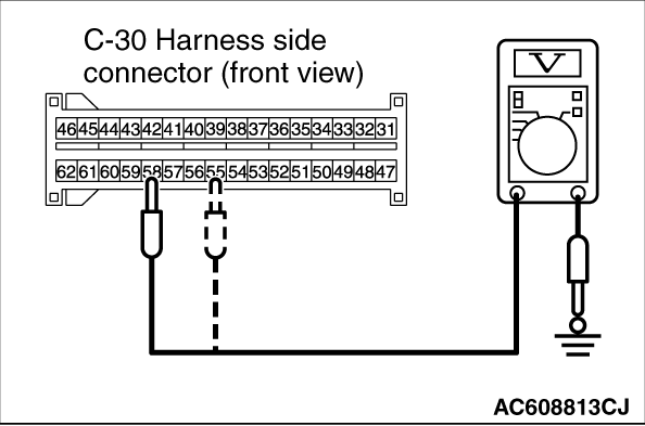
(7)Measure the voltage between terminal 55, 58 and body ground (No. B1B55 only).
Voltage should measure 1 volt or less.
Q.
Is the check result normal?
Go to Step 5.
Go to Step 4.
|
|
|
STEP 4. Check the harness wires between SRS-ECU connector C-30 (terminal
No.55 and 58) and the seat belt buckle switch (passenger’s side) connector D-33 (terminal
No.1 and 2) (No. B1B56 only).
|
|
|
Q.
Is the check result normal?
|
|
|
Go to Step 6.
|
|
|
|
|
|
Repair the harness wires between SRS-ECU connector C-30 and the seat belt buckle
switch (passenger’s side) connector D-33. Then go to Step 6.
|
|
|
|
|
|
STEP 5. Check the harness wires between SRS-ECU connector C-30 (terminal
No.55 and 58) and the seat belt buckle switch (passenger’s side) connector D-33 (terminal
No.1 and 2).
|
|
|
(1)Disconnect the negative battery terminal.
|
|
(2)While pushing the part "A" indicated in the figure of the harness side connector, turn
the lock lever to the direction of the arrow to release the lock lever, and disconnect the C-30
SRS-ECU connector.
(3)Disconnect the seat belt buckle switch (passenger’s side) connector D-33.
|
|
(4)
| caution |
Do not insert a probe into the terminal from D-33
harness side connector front side directly, as the connector contact pressure may be weakened.
|
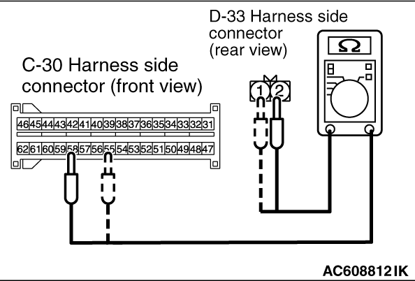
Check for continuity between the following terminals. It should be less than 2 ohms.
- SRS-ECU connector C-30 (terminal No.55) and the seat belt buckle switch (passenger’s
side) connector D-33 (terminal No.1)
- SRS-ECU connector C-30 (terminal No.58) and the seat belt buckle switch (passenger’s side)
connector D-33 (terminal No.2)
Q.
Is the check result normal?
go to Step 6.
Repair harness wires between SRS-ECU connector C-30 and the seat belt buckle switch
(passenger’s side) connector D-33.
|
|
|
STEP 6. Seat belt buckle switch (passenger’s side) check.
|
|
|
Refer to GROUP 52A, Front Seat Belt
|
|
|
Q.
Is the check result normal?
|
|
|
Go to Step 7.
|
|
|
|
|
|
Replace the seat belt buckle switch (passenger’s side) (Refer to GROUP
52A, Front Seat Belt ).
|
|
|
|
|
|
STEP 7. Recheck for diagnostic trouble code.
|
|
|
Check again if the DTC is set.
|
|
|
(2)Turn the ignition switch to the "ON" position.
|
|
|
(3)Check if the DTC is set.
|
|
|
(4)Turn the ignition switch to the "LOCK" (OFF) position.
|
|
|
Q.
Is DTC B1B54, B1B55 or B1B56 set?
|
|
|
Replace the SRS-ECU (Refer to ).
|
|
|
|
|
|
The procedure is complete.
|
|
|
|
)
)
)
)
)
)
)
)