![[Previous]](../../../buttons/fprev.png)
![[Next]](../../../buttons/fnext.png)
DTC U0171: Front
Impact Sensor (RH) Communication Error
| caution |
If DTC U0171 is set in the SRS-ECU, always diagnose the CAN
main bus line.
|
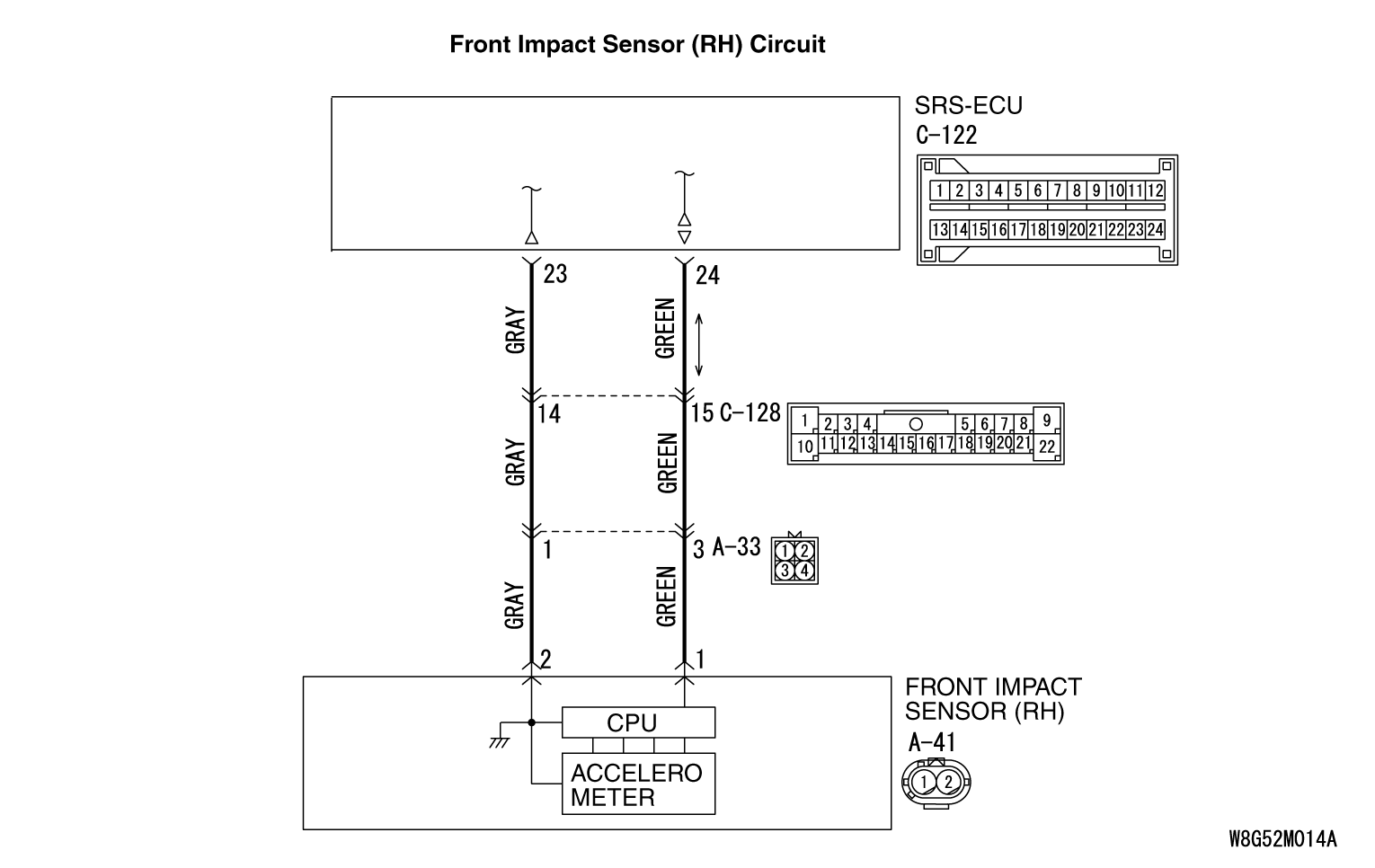
CIRCUIT OPERATION
If an impact of set value or more is detected, the front impact sensor sends the coded
acceleration data to SRS-ECU. Based on the acceleration data, SRS-ECU determines the necessity
of driver’s and front passenger’s air bag deployment, and then turns ON the
power supply circuit to the inflator.
DTC SET CONDITIONS
These DTCs are set if communication between the front impact sensor (RH) and the SRS-ECU
is not possible or faulty.
TROUBLESHOOTING HINTS
- Damaged wiring harnesses or connectors
- Malfunction of the front impact sensor (RH)
- Malfunction of the SRS-ECU
|
|
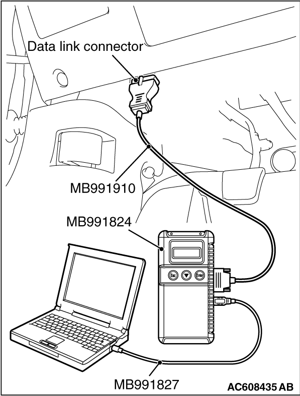
Required Special Tools:
- MB991958: Scan Tool (M.U.T.-III Sub Assembly)
- MB991824: Vehicle Communication Interface (V.C.I.)
- MB991827: M.U.T.-III USB Cable
- MB991910: M.U.T.-III Main Harness A (Vehicles with CAN communication system)
|
|
|
STEP 1. Using scan tool MB991958, diagnose the CAN bus line.
|
|
(1)
| caution |
To prevent damage to scan tool MB991958, always turn the ignition switch to the "LOCK"
(OFF) position before connecting or disconnecting scan tool MB991958.
|
Connect scan tool MB991958. Refer to "How to connect the scan tool  ." ."
(2)Turn the ignition switch to the "ON" position.
(3)Diagnose the CAN bus line.
(4)Turn the ignition switch to the "LOCK" (OFF) position.
Q.
Is the CAN bus line found to be normal?
 Go to Step 2. Go to Step 2.
 Repair the CAN bus line (Refer to GROUP 54C, Diagnosis ). Repair the CAN bus line (Refer to GROUP 54C, Diagnosis ).
|
|
|
STEP 2. Recheck for diagnostic trouble code.
|
|
|
Check again if the DTC is set.
|
|
|
(2)Turn the ignition switch to the "ON" position.
|
|
|
(3)Check if the DTC is set.
|
|
|
(4)Turn the ignition switch to the "LOCK" (OFF) position.
|
|
|
Go to Step 3.
|
|
|
|
|
|
There is an intermittent malfunction such as poor engaged connector(s) or open
circuit (Refer to GROUP 00, How to Cope with Intermittent Malfunction ).
|
|
|
|
|
|
STEP 3. Check for any diagnostic trouble code.
|
|
|
Check the front impact sensor (RH).
|
|
|
(1)Disconnect the negative battery terminal.
|
|
|
(2)Alternate the front impact sensor (RH) and front impact sensor (LH), and then install
the alternated sensors.
|
|
|
(3)Connect the negative battery terminal.
|
|
|
(4)Erase diagnostic trouble code from memory, and check the diagnostic trouble code.
|
|
|
Replace the front impact sensor (RH) with a new one (Refer to ).
Go to Step 5.
|
|
|
|
|
|
Go to Step 4.
|
|
|
|
|
|
STEP 4. Check the harness wires for open circuit and short circuit
between SRS-ECU connector C-122 (terminal No.23 and 24) and front impact sensor (RH) connector
A-41 (terminal No.2 and 1).
|
|
|
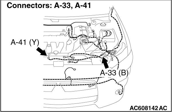
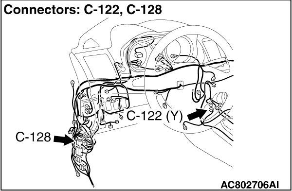
| note |
After inspecting intermediate connector A-33, C-128 inspect the wiring harness. If the
intermediate connector A-33, C-128 is damaged, repair or replace it.
|
|
|
|
Q.
Are the harness wires between SRS-ECU connector C-122 (terminal No.23 and 24) and
front impact sensor (RH) connector A-41 (terminal No.2 and 1) in good condition?
|
|
|
EGo to Step 5.
|
|
|
|
|
|
Repair the harness wires between SRS-ECU connector C-122 and front impact sensor
(RH) connector A-41.
|
|
|
|
|
|
STEP 5. Recheck for diagnostic trouble code.
|
|
|
Check again if the DTC is set.
|
|
|
(2)Turn the ignition switch to the "ON" position.
|
|
|
(3)Check if the DTC is set.
|
|
|
(4)Turn the ignition switch to the "LOCK" (OFF) position.
|
|
|
Replace the SRS-ECU (Refer to ).
|
|
|
|
|
|
There is an intermittent malfunction such as poor engaged connector(s) or open
circuit (Refer to GROUP 00, How to Cope with Intermittent Malfunction ).
|
|
|
|
)
)
)
)