![[Previous]](../../../buttons/fprev.png)
![[Next]](../../../buttons/fnext.png)
DTC B1B23: Curtain
Air Bag Module (RH) (Squib) System (Short Circuit between Squib Circuit Terminals)

| caution |
If DTC B1B23 is set in the SRS-ECU, always diagnose the CAN
main bus line.
|
CIRCUIT OPERATION
- The SRS-ECU judges how severe a collision is by detecting
signals from the side impact sensors installed on the lower side of the center pillar. If the
impact is over a predetermined level, the SRS-ECU sends an ignition signal. At this time, if the
side collision safing G-sensor is on, the SRS air bag will inflate.
- The ignition signal is input to the curtain air bag module (RH) to inflate the curtain
air bag.
DTC SET CONDITIONS
This DTC is set if there is abnormal resistance between the input terminals of the curtain
air bag module (RH) (squib).
TROUBLESHOOTING HITS
- Improper engaged connector or defective short spring*
- Short circuit between the curtain air bag module (RH) (squib) circuit terminals
- Damaged connector(s)
- Malfunction of the SRS-ECU
| note |
*: The squib circuit connectors integrate a "short" spring (which prevents the
air bag from deploying unintentionally due to static electricity by shorting the positive wire
to the ground wire in the squib circuit when the connectors are disconnected) (Refer to  ).
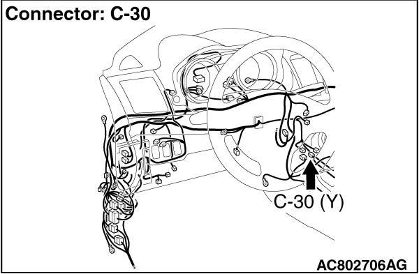
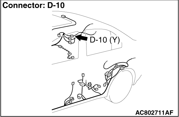
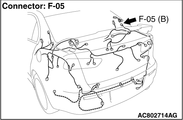
Therefore, if connector C-30, D-10 or F-05 is damaged or improperly engaged, the short spring
may not be released when the connector is connected. ).
Therefore, if connector C-30, D-10 or F-05 is damaged or improperly engaged, the short spring
may not be released when the connector is connected.
|
|
|
Required Special Tools:
- MB991958 Scan Tool (M.U.T.-III Sub Assembly)
- MB991824: Vehicle Communication Interface (V.C.I.)
- MB991827 M.U.T.-III USB Cable
- MB991910 M.U.T.-III Main Harness A (Vehicles with CAN Communication System)
- MB991865: Dummy resistor
- MB991866: Resister harness
|
|
|
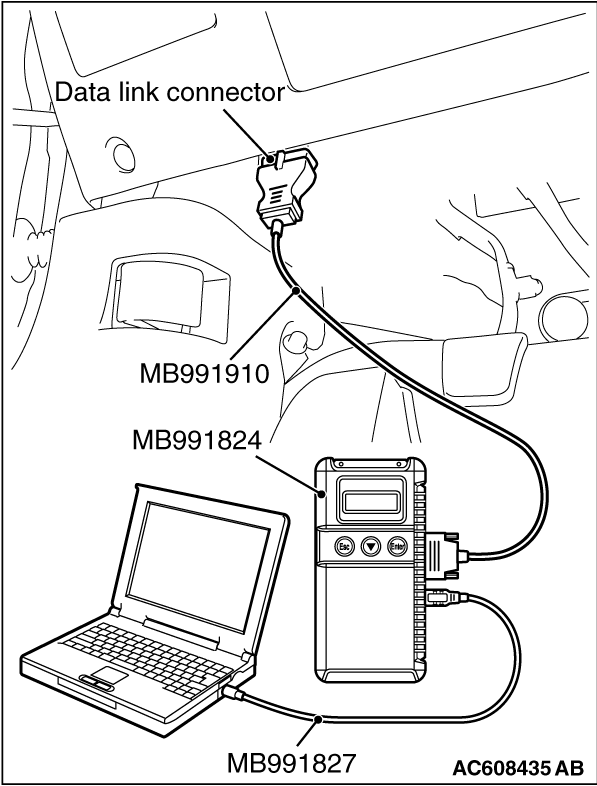
STEP 1. Using scan tool MB991958, diagnose the CAN bus line.
|
|
(1)
| caution |
To prevent damage to scan tool MB991958, always turn the ignition switch
to the "LOCK" (OFF) position before connecting or disconnecting scan tool MB991958.
|
Connect scan tool MB991958. Refer to "How to connect the scan tool ."
(2)Turn the ignition switch to the "ON" position.
(3)Diagnose the CAN bus line.
(4)Turn the ignition switch to the "LOCK" (OFF) position.
Q.
Is the CAN bus line found to be normal?
 Go to Step 2. Go to Step 2.
 Repair the CAN bus line (Refer to GROUP 54C, Diagnosis ). Repair the CAN bus line (Refer to GROUP 54C, Diagnosis ).
|
|
|
STEP 2. Recheck for diagnostic trouble code.
|
|
|
Check again if the DTC is set.
|
|
|
(2)Turn the ignition switch to "ON" position.
|
|
|
(3)Check if the DTC is set.
|
|
|
(4)Turn the ignition switch to the "LOCK" (OFF) position.
|
|
|
Go to Step 3.
|
|
|
|
|
|
There is an intermittent malfunction such as poor engaged connector(s) or open
circuit (Refer to GROUP 00, How to Use Troubleshooting/Inspection Service Points -
How
to Cope with Intermittent Malfunctions ).
|
|
|
|
|
|
STEP 3. Check SRS-ECU connector C-30, curtain air bag module (RH)
connector F-05 and intermediate connector D-10.
|
|
|
(1)Disconnect the negative battery terminal.
|
|
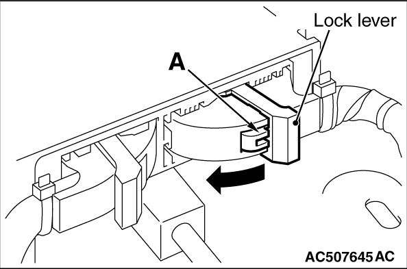
(2)While pressing the part A in the illustration of the C-30 SRS-ECU harness side connector,
turn the lock lever toward the arrow direction to release the lock lever. Then, disconnect the
connector and reconnect it.
|
|
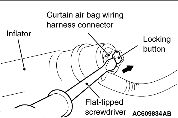
(3)Disconnect the F-05 connector, and then reconnect it. Use a flat-tipped (-) screwdriver
to pull out the F-05 curtain air bag module harness side connector locking button toward the
arrow direction, release the lock, and then disconnect the connector.
|
|
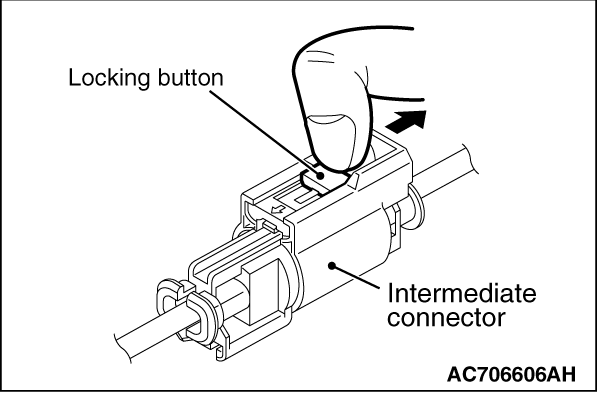
(4)Disconnect the D-10 connector’s, and then reconnect them. Unlock the connector
by sliding the locking button to the direction of the arrow as shown in the figure, and then disconnect
the connector.
(5)Connect the negative battery terminal.
(6)After erasing the diagnostic trouble code memory, check the diagnostic trouble code again.
(7)Disconnect the negative battery terminal.
Q.
Is DTC B1B23 set?
Go to Step 4.
Intermittent Malfunction (Refer to GROUP 00, How to Use Troubleshooting/Inspection
Service Points -
How to Cope with Intermittent Malfunction ).
|
|
|
STEP 4. Check by dummy resistor connection.
|
|
|
(1)Disconnect the negative battery terminal.
|
|
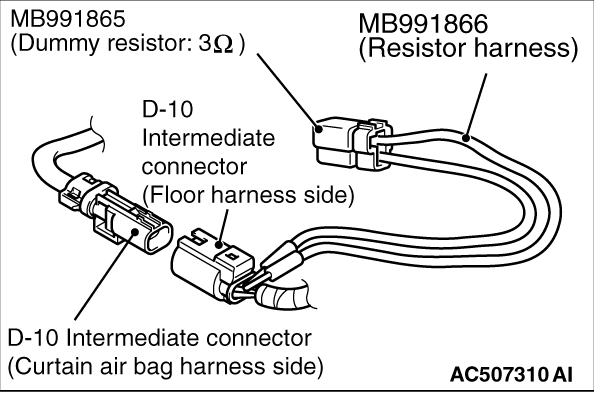
(2)Disconnect the D-10 intermediate connector unlock the connector by sliding the locking
button to the direction of the arrow as shown in the figure, and then disconnect the connector.
|
|
(3)Connect special tool MB991865 to special tool MB991866.
(4)
| caution |
Do not insert a probe into the terminal from its front side directly,
as the connector contact pressure may be weakened.
|
Insert the probe of resistor harness, to which the dummy resistor is installed, from the
back of D-10 intermediate connector (floor harness side).
(5)Connect the negative battery terminal.
(6)After erasing the diagnostic trouble code memory, check the diagnostic trouble
code again.
Q.
Is DTC B1B23 set?
Go to Step 5.
Go to Step 6.
|
|
|
STEP 5. Resistance measurement at the C-30 SRS-ECU connector.
|
|
|
(1)Disconnect the negative battery terminal.
|
|
(2)While pushing the part "A" indicated in the figure of the harness side connector, turn
the lock lever to the direction of the arrow to release the lock lever, and disconnect the C-30
SRS-ECU connector.
|
|
(3)
| danger |
To prevent the air bag from deploying unintentionally, disconnect
the intermediate connector D-10 to short the squib circuit.
|
Disconnect the D-10 intermediate connector unlock the connector by sliding the locking
button to the direction of the arrow as shown in the figure, and then disconnect the connector.
|
|
(4)
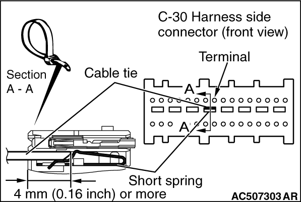
| caution |
The short spring may not be released due to the insufficient insertion.
Therefore, insert the insulator for 4 mm (0.6 inch) or more.
|
Insert a cable tie [3 mm (0.12 inch) wide, 0.5 mm (0.02 inch) thick]
between
terminal 39, 40 and the short spring to release the short spring.
|
|
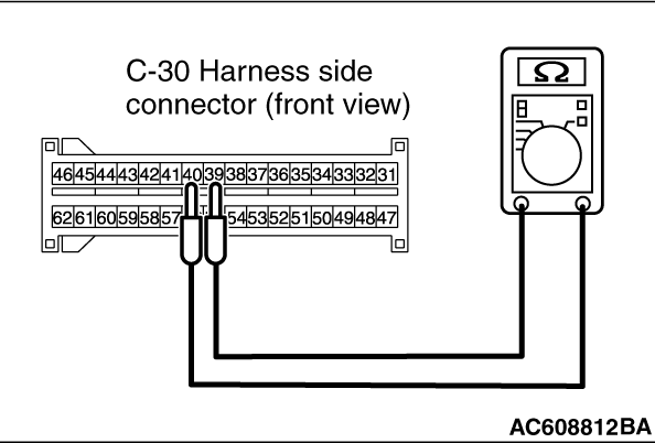
(5)Check for continuity between the C-30 wiring harness side connector terminal No. 39 and
No. 40.
It should be open circuit.
Q.
Is it open circuit?
Go to Step 7.
Repair the wiring harness.
|
|
|
STEP 6. Short circuit check between the F-05 curtain air bag module
harness side connector and the D-10 intermediate harness.
|
|
|
(1)Disconnect the negative battery terminal.
|
|
(2)
| danger |
To prevent the air bag from deploying unintentionally, disconnect
the curtain air bag module connector F-05 to short the squib circuit.
|
Disconnect curtain air bag module (RH) F-05. Use a flat-tipped screwdriver to unlock the
locking button at the harness side connector by withdrawing it toward you in two stages, and
then disconnect the connector.
|
|
(3)Disconnect the D-10 intermediate connector unlock the connector by sliding the locking
button to the direction of the arrow as shown in the figure, and then disconnect the connector.
|
|
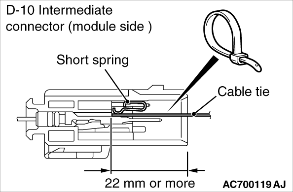
(4)Because the short spring is installed to the D-10 intermediate connector (curtain air
bag harness side), insert a cable tie [3 mm (0.12 inch) wide, 0.5 mm (0.02 inch) thick]
between
terminals 1, 2 and the short spring to release the short spring.
|
|
(5)
| caution |
Do not insert a probe into the terminal from its front side directly, as the connector
contact pressure may be weakened.
|
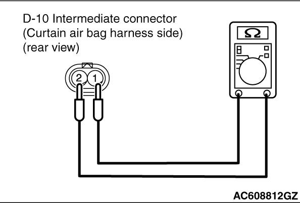
Check for continuity between the D-10 intermediate connector (curtain air bag harness
side) terminal No.1 and 2.
It should be open circuit.
Q.
Is it open circuit?
Replace the curtain air bag module (RH) (Refer to ).
Then go to Step 7.
Repair the wiring harness.
|
|
|
STEP 7. Recheck for diagnostic trouble code.
|
|
|
Check again if the DTC is set.
|
|
|
(2)Turn the ignition switch to the "ON" position.
|
|
|
(3)Check if the DTC is set.
|
|
|
(4)Turn the ignition switch to the "LOCK" (OFF) position.
|
|
|
Replace SRS-ECU (Refer to ).
|
|
|
|
|
|
Intermittent Malfunction (Refer to GROUP 00, How to Use Troubleshooting/Inspection
Service Points -
How to Cope with Intermittent Malfunction ).
|
|
|
|
)
)
)
)
)
)
)
)
)
)
)
)
)