![[Previous]](../../../buttons/fprev.png)
![[Next]](../../../buttons/fnext.png)
DTC B1B72: Malfunction of G-sensor Inside Side Impact Sensor (LH)
DTC B1B75: Malfunction of G-sensor Inside Side Impact Sensor (RH)
| caution |
If the diagnostic trouble code B1B72 or B1B75 is set in the SRS-ECU, always diagnose the CAN main bus line.
|
DTC SET CONDITIONS
These DTCs are set if the following conditions are detected from the analog G-sensor inside the side impact sensor output:
- Analog G-sensor is not operating.
- Analog G-sensor characteristics are abnormal.
- Analog G-sensor output is abnormal.
TROUBLESHOOTING HINTS
Malfunction of side impact sensor (LH) (for DTC B1B72) and side impact sensor (RH) (for DTC B1B75)
|
|
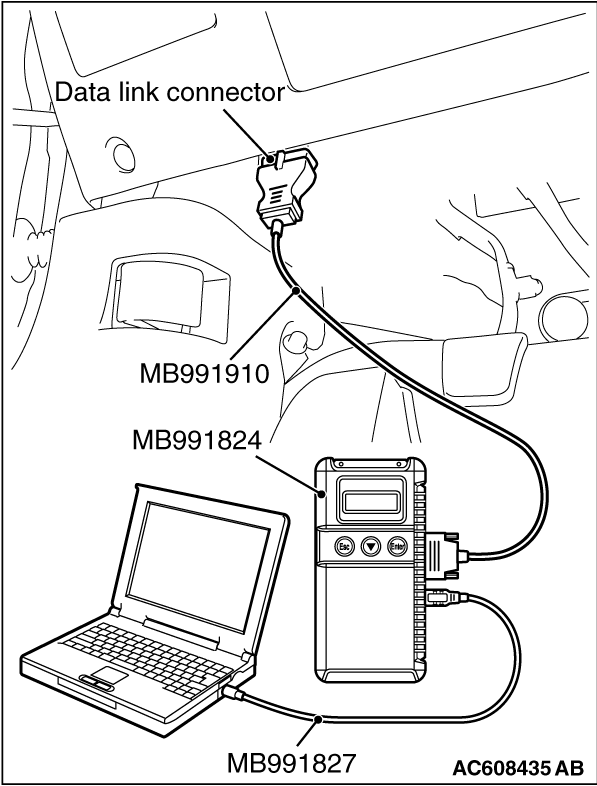
Required Special Tools:
- MB991958: Scan Tool (M.U.T.-III Sub Assembly)
- MB991824: Vehicle Communication Interface (V.C.I.)
- MB991827: M.U.T.-III USB Cable
- MB991910: M.U.T.-III Main Harness A (Vehicles with CAN communication system)
|
|
|
STEP 1. Using scan tool MB991958, diagnose the CAN bus line.
|
|
(1)
| caution |
To prevent damage to scan tool MB991958, always turn the ignition switch to the "LOCK" (OFF) position before connecting or disconnecting scan tool MB991958.
|
Connect scan tool MB991958. Refer to "How to connect the scan tool  ." ."
(2)Turn the ignition switch to the "ON" position.
(3)Diagnose the CAN bus line.
(4)Turn the ignition switch to the "LOCK" (OFF) position.
Q.
Is the CAN bus line found to be normal?
 Go to Step 2. Go to Step 2.
 Repair the CAN bus line (Refer to GROUP 54C, Diagnosis ). Repair the CAN bus line (Refer to GROUP 54C, Diagnosis ).
|
|
|
STEP 2. Check the side impact sensor.
|
|
|
(1)Disconnect the negative battery terminal.
|
|
|
(2)A side impact sensor is checked in the following way.
- Replace the left side impact sensor {In case of code B1B72 (Regardless of "Active" or "Stored" faults)} with the new part.
- Replace the right side impact sensor {In case of code B1B75 (Regardless of "Active" or "Stored" faults)} with the new part.
|
|
|
(3)Connect the negative battery terminal.
|
|
|
(4)After erasing the diagnostic trouble code memory, check the diagnostic trouble code again.
|
|
|
Q.
Is either DTC No. B1B72 or B1B75 set?
|
|
|
Go to Step 3.
|
|
|
|
|
|
The procedure is complete.
|
|
|
|
|
|
STEP 3. Check the SRS-ECU.
|
|
|
(1)Disconnect the negative battery terminal.
|
|
|
(2)Replace the SRS-ECU with a new one (Refer to ).
|
|
|
(3)Connect the negative battery terminal.
|
|
|
(4)Check the diagnosis code again.
|
|
|
Q.
Is either DTC No. B1B72 or B1B75 set?
|
|
|
Return to Step 1.
|
|
|
|
|
|
The procedure is complete.
|
|
|
|
)