|
|
To inspect and service the SRS after a collision
(whether or not the air bags have deployed), perform the following steps.
|
|
|
Required Special Tool:
- MB991958: Scan Tool (M.U.T.-III Sub Assembly)
- MB991824:Vehicle Communication Interface (V.C.I.)
- MB991827:M.U.T.-III USB Cable
- MB991910:M.U.T.-III Main Harness A (Vehicles with CAN Communication System)
|
|
1.
| caution |
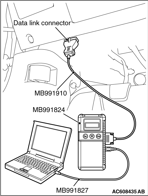
To prevent damage to scan tool MB991958, always turn the ignition switch to the "LOCK"
(OFF) position before connecting or disconnecting scan tool MB991958.
|
Connect scan tool MB991958 to the data link connector (16-pin).
2.Read (and write down) all displayed diagnostic trouble codes (Refer to SRS-ECU  ,
Occupant classification-ECU ). ,
Occupant classification-ECU ).
| note |
If the battery power supply has been disconnected or disrupted by the collision, scan
tool MB991958 cannot communicate with the SRS-ECU. Check the battery, then check and, if necessary,
repair the front wiring harness and the instrument panel wiring harness before proceeding.
|
3.Read the data list (fault duration and how many times memories are erased), using
scan tool MB991958 (Refer to ).
4.Erase the diagnostic trouble codes, and then turn the ignition switch to the LOCK
(OFF) position.
5.Wait for at least one second, and then turn the ignition switch to the ON position
again.
6.After waiting 15 seconds or more, note all displayed diagnostic trouble codes (Refer
to SRS-ECU , Occupant classification-ECU ).
|
|
|
1.Replace the following parts with new ones:
- Front impact sensors (Refer to ).
- SRS-ECU (Refer to ).
- Driver’s air bag module (Refer to ) <Except RALLIART>,
(Refer to ) <RALLIART>.
- Passenger’s (front) air bag module (Refer to ).
- Knee air bag module (Refer to ).
- Seat belt with pre-tensioner (Refer to ).
- Instrument panel assembly (Refer to GROUP 52A, Instrument Panel Assembly ).
- Front seat cushion frame (RH) (Refer to GROUP 52A, Front Seat Assembly ) <Except
RALLIART>, slide adjuster (RH) (Refer to GROUP 52A, Front Seat Assembly ) <RALLIART>.
|
|
|
2.Check the following parts and replace if there are any malfunctions:
- Clock spring (Refer to ) <Except RALLIART>,
(Refer to ) <RALLIART>.
- Seat slide sensor
- Seat belt switch (Refer to GROUP 52A, Front Seat Belt, Inspection ).
- Steering wheel, steering column shaft assembly
(1)
Check the wiring harness (built into the steering wheel) and connectors for damage,
and terminals for deformation.
(2)
Install the air bag module to check fit and alignment with the steering wheel.
(3)
Check the steering wheel for noise, binding or difficult operation and excessive free
play.
(4)
Check the steering column shaft shock absorbing mechanism (Refer to GROUP 37, On-Vehicle
Service -
Steering Column Shaft Assembly Shock Absorbing Mechanism Check ).
|
|
|
3.Check the wiring harnesses for binding, the connectors for damage, poor connections,
and the terminals for deformation (Refer to ).
|
|
|
1.Replace the following parts with new ones:
- SRS-ECU (Refer to ).
- Side impact sensors (Refer to ).
- Front seatback assembly (Refer to ) <Except RALLIART>,
Front seatback (Refer to ) <RALLIART>.
- Front seat cushion frame (RH) (Refer to GROUP 52A, Front Seat Assembly ) <Except
RALLIART>, slide adjuster (RH) (Refer to GROUP 52A, Front Seat Assembly ) <RALLIART>.
- Curtain air bag module (Refer to ).
|
|
|
2.Check the wiring harnesses for binding, the connectors for damage, poor connections,
and the terminals for deformation (Refer to ).
|
|
|
Check the SRS components. If the SRS components are showing any visible damage such as
dents, cracks, or deformation, replace them with new ones. Concerning parts removed for inspection,
replacement with new parts and cautionary points for working, refer to appropriate INDIVIDUAL COMPONENT
SERVICE .
|
|
1.Check the headlight support panel upper for distortion and rust.
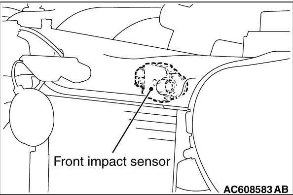
2.Check the front impact sensor for dents, cracks, deformation or rust.
3.Check the front impact sensor wiring harness for binding, check the connector for
damage, and check the terminals for deformation.
| note |
The illustration shows the side impact sensor (LH). The position of the side impact sensor
(RH) is symmetrical to this.
|
|
|
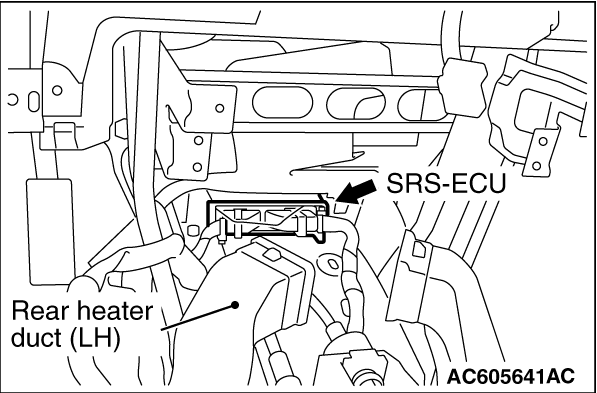
1.Check the SRS-ECU case and brackets for dents, cracks or deformation.
2.Check the connector for damage, and the terminals for deformation.
3.Check the installation of the SRS-ECU and its bracket.
|
|
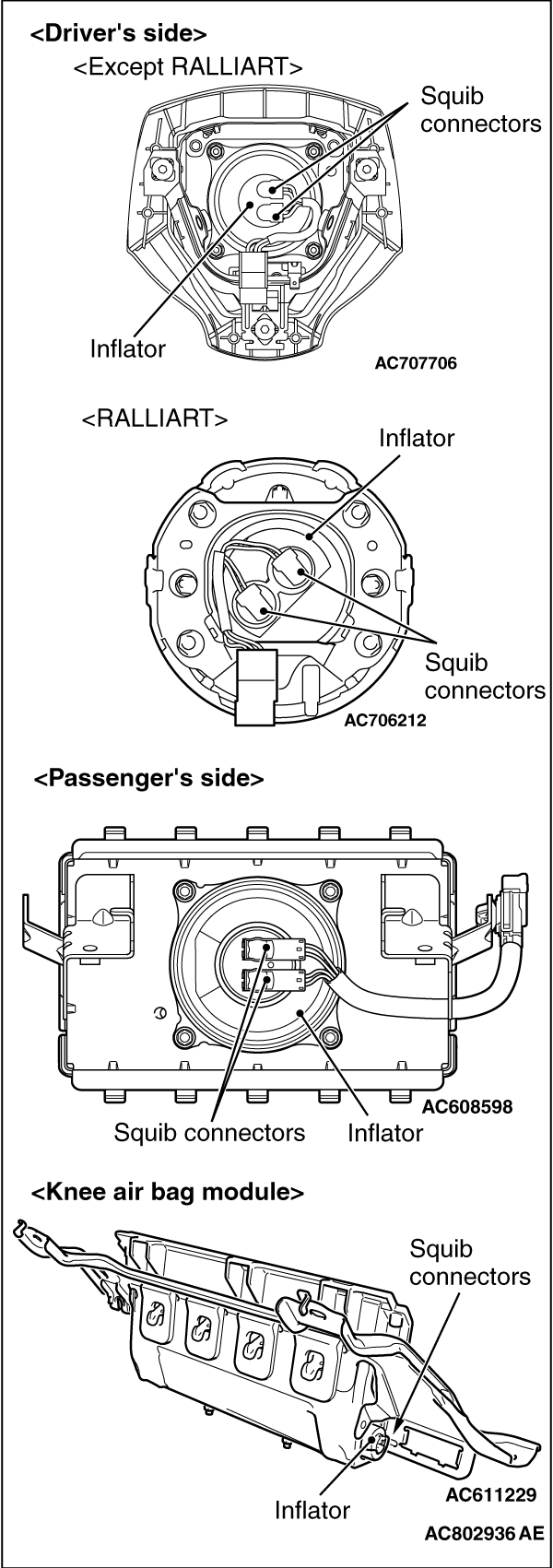
1.Check the pad cover for dents, cracks or deformation.
2.Check the connector for damage, terminal deformities, and the harness for binding.
3.Check the air bag inflator case for dents, cracks or deformities.
4.Install the air bag module (driver’s side) to the steering wheel to check
installation or alignment with the steering wheel.
5.Install the air bag module (front passenger’s side) to the instrument panel
and front deck crossmember to check installation or alignment.
|
|
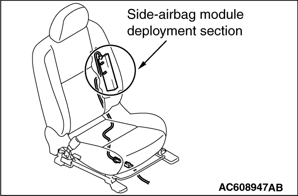
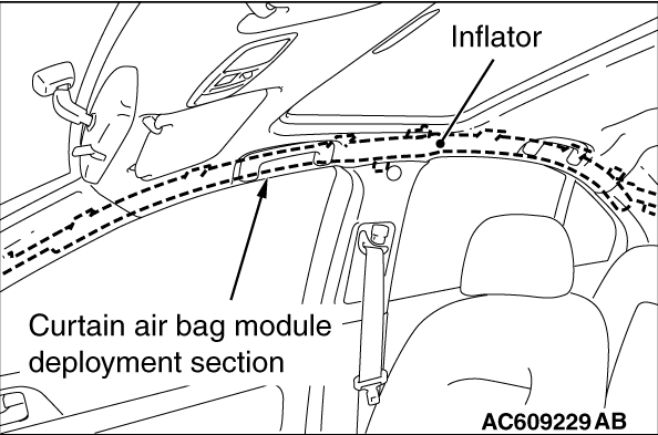
1.Check the air bag module deployment section for dents or deformation.
2.Check that there is no connector damage, bent terminals or harness crimping.
|
|
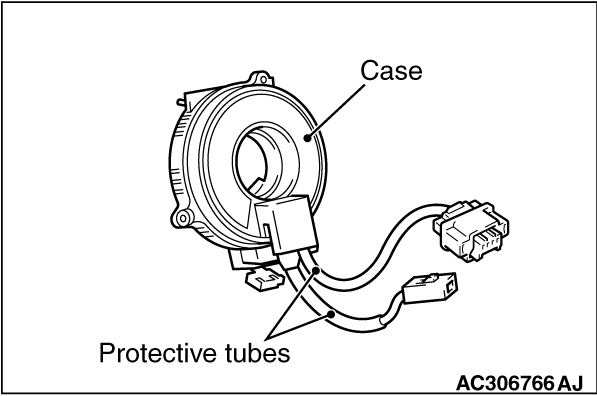
1.Check the clock spring connectors and protective tube for damage, and the terminals for
deformation.
2.Visually check the case for damage.
3.Check for continuity between the connectors (Refer to ) <Except
RALLIART>, (Refer to ) <RALLIART>
|
|
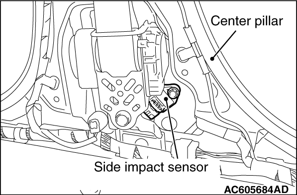
1.Check that there is no bending or corrosion in the center pillar.
2.Check that there is no denting, breakage or bending of the side impact sensor.
3.Check that there is no harness crimping, connector damage or bent terminals.
| note |
The illustration shows the side impact sensor (LH). The position of the side impact sensor
(RH) is symmetrical to this.
|
|
|
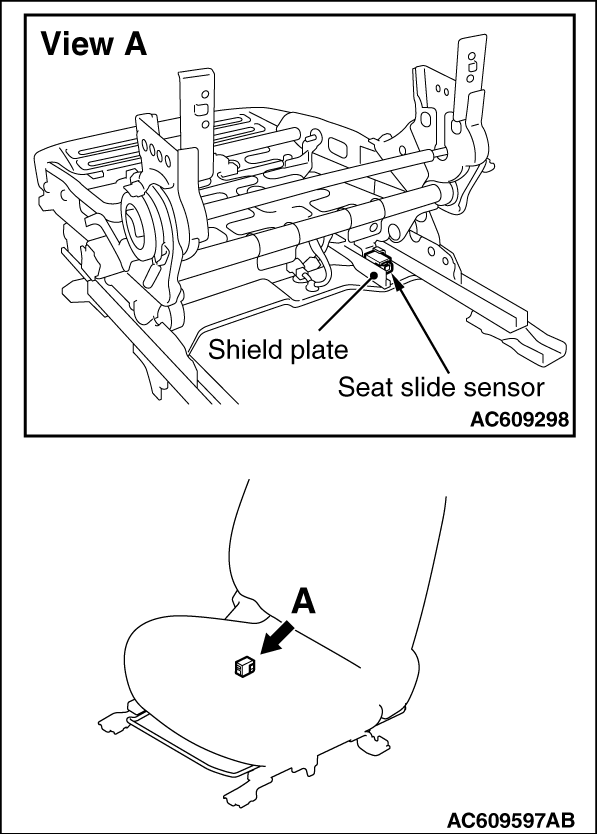
1.Check that there is no connector damage, bent terminals or harness crimping.
2.Check the installation of the seat slide sensor.
|
|
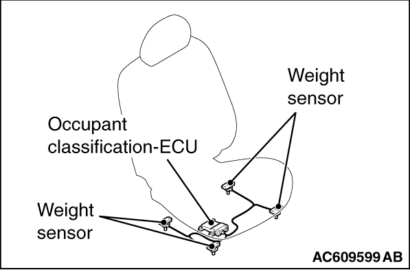
1.Check the occupant classification-ECU case and weight sensor for dents, cracks or deformation.
2.Check the connector for damage, and the terminals for deformation.
3.Check the installation of the occupant classification-ECU and weight sensor.
4.Check the diagnostic trouble code of the occupant classification-ECU and replace the
front seat cushion frame (RH) <Except RALLIART>, slide adjuster (RH) <RALLIART>. if
DTC B1BA7 is set.
|
|
1.Check that the curtain air bag deployment part of the headlining is normal.
2.Check the inflator surface for cracks, dents or deformations.
3.Check the connector for damage, the terminal for deformation, and the harness for
binding.
|
|
|
1.Check the wiring harness (built into the steering wheel) and the connectors for damage,
and the terminals for deformation.
|
|
|
2.Install the air bag module to check fit or alignment with the steering wheel.
|
|
|
3.Check the steering wheel for noise, binding or difficult operation and excessive free
play.
|
|
|
4.Check the steering column shaft shock absorbing mechanism (Refer to GROUP 37, On-Vehicle
Service -
Steering Column Shaft Assembly Shock Absorbing Mechanism Check ).
|
|
|
1.Check the seat belt for damage or deformation.
|
|
|
2.Check the seat belt with pre-tensioner for cracks or deformation.
|
|
|
3.Check that the unit is installed correctly to the vehicle body.
|
|
|
Check the harnesses for binding, the connectors for damage, poor connection, and the terminals
for deformation (Refer to ).
|
![[Previous]](../../../buttons/fprev.png)
![[Next]](../../../buttons/fnext.png)
)
)
)
)
)
)
)
)
)
)