|
|
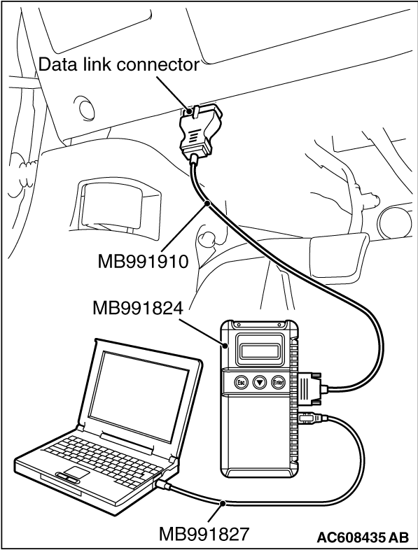
Required Special Tools:
- MB992006: Extra fine probe
- MB991223: Harness set
- MB991958: Scan Tool (M.U.T.-III Sub Assembly)
- MB991824: Vehicles Communication Interface (V.C.I.)
- MB991827: M.U.T.-III USB Cable
- MB991910: M.U.T.-III Main Harness A
|
|
(1)
| caution |
To prevent damage to scan tool MB991958, always turn the ignition switch
to the "LOCK" (OFF) position before connecting or disconnecting scan tool MB991958.
|
Connect scan tool MB991958. Refer to "How to connect scan tool (M.U.T.-III)  ." ."
(2)Turn the ignition switch to the "ON" position.
(3)Check whether the KOS-ECU related DTC is set.
(4)Turn the ignition switch to the "LOCK" (OFF) position.
Q.
Is the DTC set?
 Diagnose the KOS-ECU. Refer to . Diagnose the KOS-ECU. Refer to .
 Go to Step 2. Go to Step 2.
|
|
|
Q.
Is KOS-ECU connector C-31 in good condition?
|
|
|
Repair or replace the damaged component(s). Refer to GROUP 00E, Harness Connector
Inspection . Check that the inside and outside antenna works
normally.
|
|
|
|
|
|
- Wiring harness between KOS-ECU connector C-31 (terminal
No. 40) and outside transmitter antenna assembly (driver’s side) D-19 connector (terminal
No. 1)
- Wiring harness between KOS-ECU connector C-31 (terminal No. 40) and outside transmitter
antenna assembly (passenger’s side) connector D-38 (terminal No. 1)
- Wiring harness between KOS-ECU connector C-31 (terminal No. 40) and inside transmitter
antenna (front) connector C-116 (terminal No. 1)
- Wiring harness between KOS-ECU connector C-31 (terminal No. 40) and inside transmitter
antenna (rear) connector F-03 (terminal No. 1)
- Wiring harness between KOS-ECU connector C-31 (terminal No. 40) and outside transmitter
antenna assembly (trunk lid) connector F-16 (terminal No. 3)
|
|
|
Q.
Is the check result normal?
|
|
|
Repair the wiring harness.
|
|
|
|
|
|
(2)Turn the ignition switch from the LOCK (OFF) position to the ON position.
|
|
|
(3)Check if the DTC is set.
|
|
|
Replace KOS-ECU and register the ID codes (Refer to ).
|
|
|
|
|
|
The diagnosis is complete.
|
|
|
|
![[Previous]](../../../buttons/fprev.png)
![[Next]](../../../buttons/fnext.png)
)
)
)
)
)
)
)