|
|
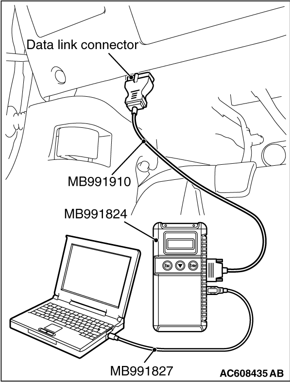
Required Special Tools:
- MB991958: Scan Tool (M.U.T.-III Sub Assembly)
- MB991824: Vehicle Communication Interface (V.C.I.)
- MB991827: M.U.T.-III USB Cable
- MB991910: M.U.T.-III Main Harness A (Vehicles with CAN communication system)
|
|
(1)
| caution |
To prevent damage to scan tool (MB991958), always turn the ignition switch to the "LOCK" (OFF)
position before connecting or disconnecting scan tool (MB991958).
|
Connect scan tool MB991958 to the data link connector.
(2)Turn the ignition switch to the "ON" position.
(3)Diagnose the CAN bus line.
(4)Turn the ignition switch to the "LOCK" (OFF) position.
Q.
Is the CAN bus line found to be normal?
 Go to Step 2. Go to Step 2.
 Repair the CAN bus line. (Refer to GROUP 54C, Diagnosis Repair the CAN bus line. (Refer to GROUP 54C, Diagnosis  ). ).
|
|
|
Q.
Is ETACS-ECU connector C-317 and WCM connector C-09 in good condition?
|
|
|
Repair the defective connector.
|
|
|
|
|
|
- Check the power supply line for open circuit.
|
|
|
Q.
Is the wiring harness between WCM connector C-09 (terminal No. 9) and ETACS-ECU connector
C-317 (terminal No. 5) in good condition?
|
|
|
The wiring harness may be damaged or the connector(s) may have loose, corroded
or damaged terminals, or terminals pushed back in the connector.
|
|
|
|
|
|
Use the ETACS-ECU data list to check the signals related to the ignition voltage.
|
|
|
Turn the ignition switch from "LOCK" (OFF) position to "ON" position.
|
|
|
Q.
Does scan tool MB991958 display the item "IG voltage" as normal condition?
|
|
|
Diagnose the ETACS-ECU. Refer to GROUP 54A, Diagnosis .
|
|
|
|
|
|
Check again if the DTC is set to the WCM.
|
|
|
(2)Turn the ignition switch from "LOCK" (OFF) position to "ON" position.
|
|
|
(4)Turn the ignition switch to the "LOCK" (OFF) position.
|
|
|
Replace WCM and register the ID codes. (Refer to .)
|
|
|
|
|
|
The trouble can be an intermittent malfunction (Refer to GROUP 00 - How
to use Troubleshooting/inspection Service Points - How to Cope with Intermittent Malfunction ).
|
|
|
|
![[Previous]](../../../buttons/fprev.png)
![[Next]](../../../buttons/fnext.png)
)
)
)
)