|
|
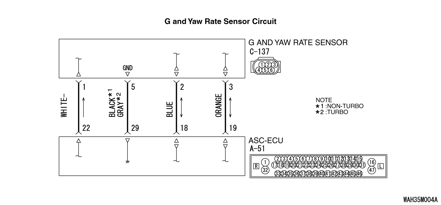
The G and yaw rate sensor outputs the signal to ASC-ECU via the special CAN bus lines.
|
|
|
This DTC is set when the ASC-ECU cannot receive the signal from the G and yaw rate sensor
although there is no abnormality in ASC-ECU supply voltage.
|
|
|
- Wiring harness or connector failure for the special CAN bus lines between
ASC-ECU and the G and yaw rate sensor
- G and yaw rate sensor malfunction
- ASC-ECU malfunction
- External noise interference
- Connector disconnected or improperly connected
- Stretched or broken wires
|
|
|
Required Special Tools:
- MB991958: Scan Tool (M.U.T.-III Sub Assembly)
- MB991824: Vehicle Communication Interface (V.C.I.)
- MB991827: M.U.T.-III USB Cable
- MB991910: M.U.T.-III Main Harness A
|
|
|
Use M.U.T.-III to diagnose the CAN bus lines.
|
|
|
Q.
Is the check result normal?
|
|
|
 Repair the CAN bus lines. (Refer to GROUP 54C - CAN Bus Diagnostic table Repair the CAN bus lines. (Refer to GROUP 54C - CAN Bus Diagnostic table  .)
On completion, go to Step 2. .)
On completion, go to Step 2.
|
|
|
|
|
|
 The procedure is complete. The procedure is complete.
|
|
|
|
|
|
Q.
Is the check result normal?
|
|
|
 Repair the connector, and then go to Step 7. Repair the connector, and then go to Step 7.
|
|
|
|
|
|
- Check the communication circuit for open and short circuit.
|
|
|
Q.
Is the check result normal?
|
|
|
 Repair the wiring harness, and then go to Step 7. Repair the wiring harness, and then go to Step 7.
|
|
|
|
|
|
 Replace the G and yaw rate sensor.(Refer to Replace the G and yaw rate sensor.(Refer to  .)
Then go to Step 6. .)
Then go to Step 6.
|
|
|
|
|
|
 Intermittent malfunction (Refer to GROUP 00 - How to Cope with Intermittent
Malfunction Intermittent malfunction (Refer to GROUP 00 - How to Cope with Intermittent
Malfunction  .) .)
|
|
|
|
|
|
 Replace the hydraulic unit (integrated with ASC-ECU). (Refer to Replace the hydraulic unit (integrated with ASC-ECU). (Refer to  .)
Then go to Step 7. .)
Then go to Step 7.
|
|
|
|
|
|
 The procedure is complete. The procedure is complete.
|
|
|
|
|
|
 The procedure is complete. The procedure is complete.
|
|
|
|
![[Previous]](../../../buttons/fprev.png)
![[Next]](../../../buttons/fnext.png)


 Go to Step 3.
 Repair the CAN bus lines. (Refer to GROUP 54C - CAN Bus Diagnostic table
  .)
On completion, go to Step 2.
 Go to Step 3.
 The procedure is complete.
 Go to Step 4.
 Repair the connector, and then go to Step 7.
 Go to Step 5.
 Repair the wiring harness, and then go to Step 7.
 Replace the G and yaw rate sensor.(Refer to
  .)
Then go to Step 6.
 Intermittent malfunction (Refer to GROUP 00 - How to Cope with Intermittent
Malfunction
  .)
.) Replace the hydraulic unit (integrated with ASC-ECU). (Refer to
  .)
Then go to Step 7.
 The procedure is complete.
 Return to Step 1.
 The procedure is complete.