![[Previous]](../../../buttons/fprev.png)
![[Next]](../../../buttons/fnext.png)
DTC C2114 Abnormality
in G and yaw rate sensor operation voltage (Low voltage)
DTC C2115 Abnormality in G
and yaw rate sensor operation voltage (High voltage)
|
|
| caution |
- If there is
any problem in the CAN bus lines, an incorrect DTC may be set. Prior to this diagnosis, diagnose
the CAN bus lines (Refer to GROUP 54C - Diagnostic trouble code diagnosis
 ). ).
- Whenever ECU is replaced, ensure that the CAN bus lines are normal.
- Do not drop or shock the G and yaw rate sensor.
- When the G and yaw rate sensor is replaced, always carry out calibration to make
ASC-ECU learn the neutral point (Refer to ).
- When the hydraulic unit (integrated with ASC-ECU) is replaced, always carry out
the calibration of the steering wheel sensor, the G and yaw rate sensor and brake fluid pressure
sensor (Refer to , and ).
|
|
|
|
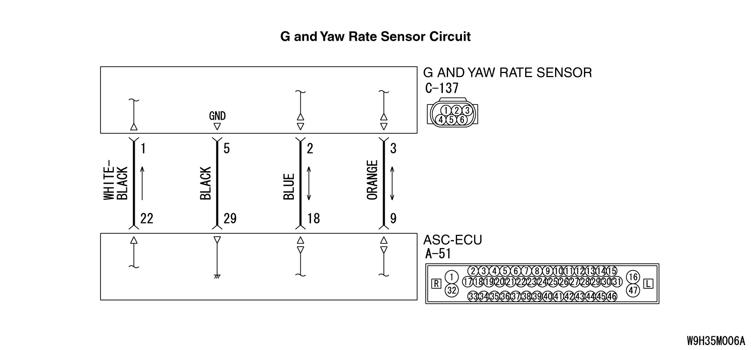
- ASC-ECU supplies power to the G and yaw rate sensor at the terminal No.1.
- The G and yaw rate sensor outputs the signal to ASC-ECU via the special CAN bus
lines.
|
|
|
This DTC is set if any malfunction below is found:
|
|
|
DTC C2114
- When the power supply voltage applied from ASC-ECU to the G and yaw rate sensor
is not within the standard value range (low)
|
|
|
DTC C2115
- When the power supply voltage applied from ASC-ECU to the G and yaw rate sensor
is not within the standard value range (high)
|
|
|
- Wiring harness or connector failure for the special CAN bus lines between
ASC-ECU and the G and yaw rate sensor
- Damaged wiring harness and connectors
- G and yaw rate sensor malfunction
- ASC-ECU malfunction
|
|
|
Required Special Tools:
- MB991958: Scan Tool (M.U.T.-III Sub Assembly)
- MB991824: Vehicle Communication Interface (V.C.I.)
- MB991827: M.U.T.-III USB Cable
- MB991910: M.U.T.-III Main Harness A
|
|
|
STEP 1. M.U.T.-III CAN bus diagnosis
|
|
|
Use scan tool to diagnose the CAN bus lines.
|
|
|
Q.
Is the check result normal?
|
|
|
 Go to Step 2. Go to Step 2.
|
|
|
|
|
|
 Repair the CAN bus lines (Refer to GROUP 54C - CAN Bus Diagnosis table ).
On completion, go to Step 2. Repair the CAN bus lines (Refer to GROUP 54C - CAN Bus Diagnosis table ).
On completion, go to Step 2.
|
|
|
|
|
|
Check that the DTC U0125 is set in ASC-ECU.
|
|
|
Troubleshoot for the DTC (Refer to ). Then go to
Step 3.
|
|
|
|
|
|
Go to Step 3.
|
|
|
|
|
|
Q.
Are DTCs C2114 or C2115 set?
|
|
|
Go to Step 4.
|
|
|
|
|
|
The procedure is complete.
|
|
|
|
|
|
STEP 4. M.U.T.-III data list
|
|
|
Check the following service data (Refer to ).
|
|
|
- Item 08: Lateral G sensor
- Item 09: G sensor
- Item 12: Yaw rate sensor
|
|
|
Q.
Is the check result normal?
|
|
|
Go to Step 12.
|
|
|
|
|
|
Go to Step 5.
|
|
|
|
|
|
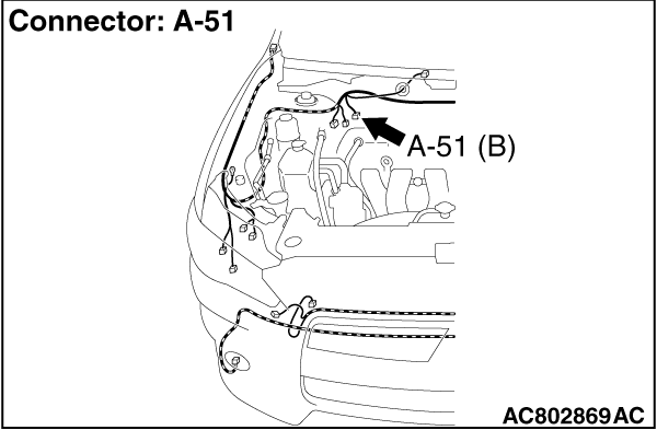
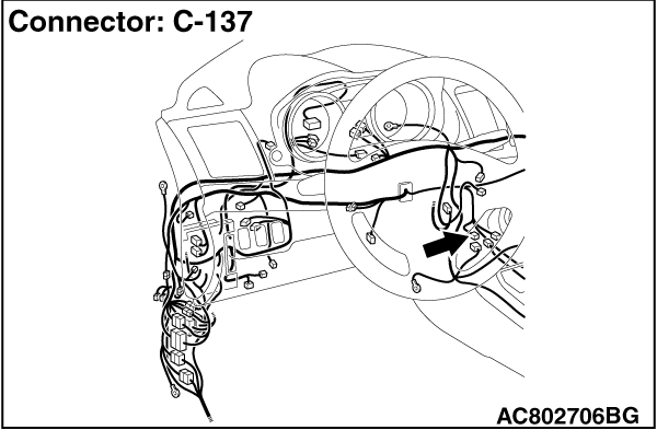
STEP 5. Connector check: A-51 ASC-ECU connector, C-137 G and yaw rate
sensor connector
|
|
|
Q.
Is the check result normal?
|
|
|
Go to Step 6.
|
|
|
|
|
|
Repair the connector, and then go to Step 13.
|
|
|
|
|
|
STEP 6. Wiring harness check between A-51 ASC-ECU connector terminal
No. 18 and C-137 G and yaw rate sensor connector terminal No. 2 as well as between A-51 ASC-ECU
connector terminal No. 19 and C-137 G and yaw rate sensor connector terminal No. 3
|
|
|
- Check the communication circuit for open and short circuit.
|
|
|
Q.
Is the check result normal?
|
|
|
Go to Step 7.
|
|
|
|
|
|
Repair the wiring harness, and then go to Step 13.
|
|
|
|
|
|
STEP 7. G and yaw rate sensor installation check
|
|
|
Check that the G and yaw rate sensor is installed correctly.
|
|
|
Q.
Is the check result normal?
|
|
|
Go to Step 8.
|
|
|
|
|
|
Reinstall the G and yaw rate sensor correctly (Refer to ),
and then go to Step 13.
|
|
|
|
|
|
STEP 8. Voltage measurement at C-137 G and yaw rate sensor connector
|
|
|
(1)Disconnect the C-137 G and yaw rate sensor connector.
|
|
|
(2)Turn the ignition switch to the ON position.
|
|
|
(3)Measure the voltage at the harness side between the terminal No.1 and the body
ground.
OK: Battery positive voltage
|
|
|
Q.
Is the check result normal?
|
|
|
Go to Step 11.
|
|
|
|
|
|
Go to Step 9.
|
|
|
|
|
|
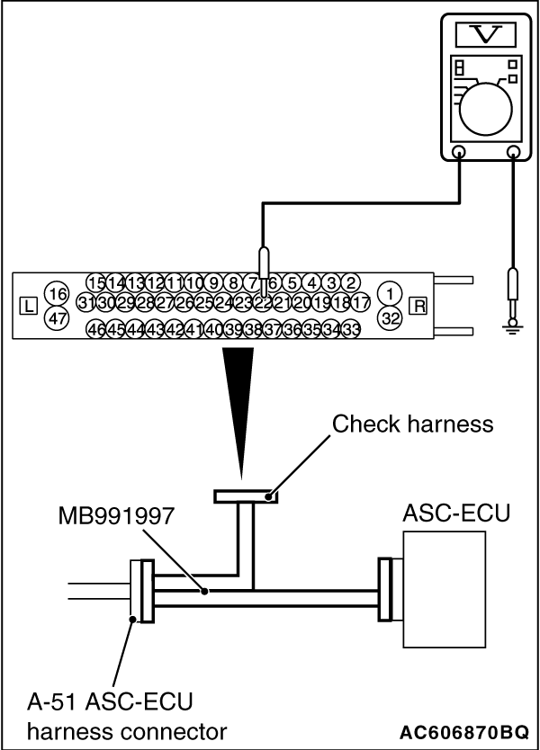
STEP 9. Voltage measurement at A-51 ASC-ECU connector
|
|
(1)Disconnect the ASC-ECU connector, connect the ASC check harness (Special tool: MB991997)
to the ASC-ECU-side connector and harness-side connector, and then measure at the special tool
connector side.
(2)Disconnect the C-137 G and yaw rate sensor connector.
(3)Turn the ignition switch to the ON position.
(4)Measure the voltage between the terminal No.22 and the body ground.
OK: Battery positive voltage
Q.
Is the check result normal?
Go to Step 10.
Go to Step 12.
|
|
|
STEP 10. Wiring harness check between A-51 ASC-ECU connector terminal
No.22 and C-137 G and yaw rate sensor connector terminal No.1.
|
|
|
- Check the power supply circuit for open or short circuit.
|
|
|
Q.
Is the check result normal?
|
|
|
Go to Step 12.
|
|
|
|
|
|
Repair the wiring harness between A-51 ASC-ECU connector terminal No. 22 and C-137
G and yaw rate sensor connector terminal No. 1.
|
|
|
|
|
|
STEP 11. Wiring harness check between A-51 ASC-ECU connector terminal
No.29 and C-137 G and yaw rate sensor connector terminal No.5.
|
|
|
- Check the ground circuit for open circuit.
|
|
|
Q.
Is the check result normal?
|
|
|
Replace the G and yaw rate sensor (Refer to ) and
then go to Step 12.
|
|
|
|
|
|
Repair the wiring harness between A-51 ASC-ECU connector terminal No.29 and C-137
G and yaw rate sensor connector terminal No.5.
|
|
|
|
|
|
STEP 12. Check whether the DTC is reset.
|
|
|
Q.
Are DTCs C2114 or C2115 set?
|
|
|
Replace the hydraulic unit (ASC-ECU) (Refer to ),
and then go to Step 13.
|
|
|
|
|
|
Intermittent malfunction (Refer to GROUP 00 - How to Cope with Intermittent
Malfunction ).
|
|
|
|
|
|
STEP 13. Check whether the DTC is reset.
|
|
|
Q.
Are DTCs C2114 or C2115 set?
|
|
|
Return to Step 1.
|
|
|
|
|
|
The procedure is complete.
|
|
|
|
)
)
)
)