![[Previous]](../../../buttons/fprev.png)
![[Next]](../../../buttons/fnext.png)
DTC C1009 Low
brake fluid level

|
|
| caution |
- If there is
any problem in the CAN bus lines, an incorrect DTC may be set. Prior to this diagnosis, diagnose
the CAN bus lines (Refer to GROUP 54C - Diagnostic trouble code diagnosis
 ). ).
- Whenever ECU is replaced, ensure that the CAN bus lines are normal.
- When the hydraulic unit (integrated with ASC-ECU) is replaced, always carry out
the calibration of the steering wheel sensor, the G and yaw rate sensor and brake fluid pressure
sensor (Refer to , and ).
|
|
|
|
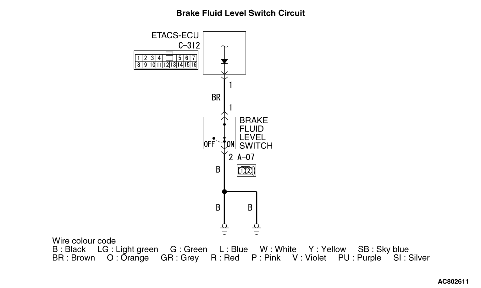
ASC-ECU receives the OFF signal of the brake fluid level switch in ETACS-ECU via the CAN
bus lines. This indicates that the brake fluid level is lower than the specified.
|
|
|
This DTC is set when the brake fluid level is lower than the specified.
|
|
|
- Low brake fluid level
- Brake fluid level switch malfunction
- Brake pad wear
- Damaged wiring harness and connectors
- Malfunction of ETACS-ECU
- ASC-ECU malfunction
|
|
|
Required Special Tools:
- MB991958: Scan Tool (M.U.T.-III Sub Assembly)
- MB991824: Vehicle Communication Interface (V.C.I.)
- MB991827: M.U.T.-III USB Cable
- MB991910: M.U.T.-III Main Harness A
|
|
|
STEP 1. M.U.T.-III CAN bus diagnostics
|
|
|
Use scan tool to diagnose the CAN bus lines.
|
|
|
Q.
Is the check result normal?
|
|
|
 Go to Step 3. Go to Step 3.
|
|
|
|
|
|
 Repair the CAN bus lines (Refer to GROUP 54C - CAN Bus Diagnostic table ).
On completion, go to Step 2. Repair the CAN bus lines (Refer to GROUP 54C - CAN Bus Diagnostic table ).
On completion, go to Step 2.
|
|
|
|
|
|
STEP 2. DTC recheck after resetting CAN bus lines
|
|
|
Go to Step 3.
|
|
|
|
|
|
The procedure is complete.
|
|
|
|
|
|
STEP 3. Brake fluid level check
|
|
|
Check that the brake fluid level is higher than the lower limit.
|
|
|
Q.
Is the check result normal?
|
|
|
Go to Step 6.
|
|
|
|
|
|
Go to Step 4.
|
|
|
|
|
|
Check that the brake pad is thicker than the limit (Refer to GROUP 35A - On-vehicle
Service, Brake Pad Check ).
|
|
|
Q.
Is the check result normal?
|
|
|
Go to Step 5.
|
|
|
|
|
|
Replace the brake pad <Refer to GROUP 35A - On-vehicle Service, Brake
Pad Replacement (Except RALLIART), (RALLIART)>,
and then add brake fluid as necessary. Then go to Step 13.
|
|
|
|
|
|
STEP 5. Brake fluid leak check
|
|
|
Check that the brake fluid is not leaking from the hydraulic unit (incorporated in ASC-ECU),
brake caliper, brake hose, brake tube, or master cylinder assembly.
|
|
|
Q.
Is the check result normal?
|
|
|
Fill the brake fluid up to the "MAX" level. Then go to Step 13.
|
|
|
|
|
|
Repair the brake fluid leak area. Then go to Step 13.
|
|
|
|
|
|
STEP 6. Brake fluid level switch check
|
|
|
Refer to GROUP 35A - On-vehicle service .
|
|
|
Q.
Is the check result normal?
|
|
|
Go to Step 7.
|
|
|
|
|
|
Replace the reservoir assembly <Refer to GROUP 35A - Master Cylinder
Assembly and Brake Booster (Except RALLIART), (RALLIART)>.
Then go to Step 13.
|
|
|
|
|
|
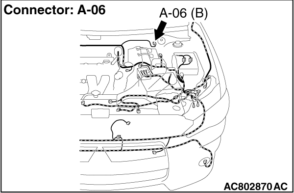
STEP 7. Connector check: A-06 brake fluid level switch connector,
C-312 ETACS-ECU connector
|
|
|
Q.
Is the check result normal?
|
|
|
Go to Step 8.
|
|
|
|
|
|
Repair the damaged connector.
|
|
|
|
|
|
STEP 8. Voltage measurement at A-06 brake fluid level switch connector
|
|
|
(1)Disconnect the connector, and measure at the wiring harness side.
|
|
|
(2)Turn the ignition switch to the ON position.
|
|
|
(3)Measure the voltage between the terminal No.1 and the body ground.
OK: Approximately 5 V
|
|
|
Q.
Is the check result normal?
|
|
|
Go to Step 10.
|
|
|
|
|
|
Go to Step 9.
|
|
|
|
|
|
STEP 9. Voltage measurement at C-312 ETACS-ECU connector
|
|
|
| caution |
With the C-312 ETACS-ECU connector kept connected, disconnect
the A-07 brake fluid level switch connector.
|
|
|
|
(1)Turn the ignition switch to the ON position.
|
|
|
(2)Measure the voltage between the terminal No.1 and the body ground to the back probing.
OK: Approximately 5 V
|
|
|
Q.
Is the check result normal?
|
|
|
Repair the wiring harness between the C-312 ETACS-ECU connector terminal No.1
and the A-06 brake fluid level switch connector terminal No.1.
|
|
|
|
|
|
Replace the ETACS-ECU (Refer to GROUP 54A - ETACS-ECU ), and
then go to Step 13.
|
|
|
|
|
|
STEP 10. Harness check: Between A-06 brake fluid level switch connector
and the body ground
|
|
|
Check the wiring harness for open circuit between the A-06 brake fluid level switch connector
terminal No.2 and the body ground.
|
|
|
Q.
Is the check result normal?
|
|
|
Go to Step 11.
|
|
|
|
|
|
Repair the wiring harness.
|
|
|
|
|
|
STEP 11. M.U.T.-III data list
|
|
|
Check the following service data (Refer to ).
|
|
|
- Item 26: Brake fluid level switch
|
|
|
Q.
Is the check result normal?
|
|
|
Go to Step 12.
|
|
|
|
|
|
Replace the ETACS-ECU (Refer to GROUP 54A - ETACS-ECU ), and
then go to Step 13.
|
|
|
|
|
|
STEP 12. Check whether the DTC is reset.
|
|
|
(2)Ignition switch "LOCK" (OFF)
|
|
|
Replace the hydraulic unit (ASC-ECU) (Refer to ). Then
go to Step 13.
|
|
|
|
|
|
The trouble can be an intermittent malfunction (Refer to GROUP 00 - How
to Cope with Intermittent Malfunction ).
|
|
|
|
|
|
STEP 13. Check whether the DTC is reset.
|
|
|
(2)Ignition switch "LOCK" (OFF)
|
|
|
Return to Step 1.
|
|
|
|
|
|
The procedure is complete.
|
|
|
|
)
)
)