![[Previous]](../../../buttons/fprev.png)
![[Next]](../../../buttons/fnext.png)
DTC C1000: Abnormality
in stoplight switch circuit
|
|
| caution |
- If there is
any problem in the CAN bus lines, an incorrect DTC may be set. Prior to this diagnosis, diagnose
the CAN bus lines (Refer to GROUP 54C -
Diagnostic trouble code diagnosis
 ). ).
- Whenever ECU is replaced, ensure that the CAN bus lines are normal.
- When the hydraulic unit (integrated with ASC-ECU) is replaced, always carry out
the calibration of the steering wheel sensor, the G and yaw rate sensor and brake fluid pressure
sensor (Refer to , and ).
|
|
|
|
ETACS-ECU sends the ON signal generated when the brake pedal is depressed and OFF signal
generated when it is released to ABS-ECU via the CAN bus lines.
|
|
|
This DTC is set in the following case.
|
|
|
- When the vehicle has run for a long time with the stoplight switch turned
ON.
- When the OFF status of the stoplight switch does not match the vehicle attitude
|
|
|
- Improper adjustment of stoplight switch installation position
- Malfunction of the stoplight switch
- Damaged wiring harness and connectors
- Malfunction of ETACS-ECU
- ASC-ECU malfunction
|
|
|
Required Special Tools:
- MB991958: Scan Tool (M.U.T.-III Sub Assembly)
- MB991824: Vehicle Communication Interface (V.C.I.)
- MB991827: M.U.T.-III USB Cable
- MB991910: M.U.T.-III Main Harness A
- MB991997: ASC check harness
|
|
|
STEP 1. Using scan tool MB991958, diagnose the CAN bus lines.
|
|
|
Use scan tool to diagnose the CAN bus lines.
|
|
|
Q.
Is the check result normal?
|
|
|
 Go to Step 3. Go to Step 3.
|
|
|
|
|
|
 Repair the CAN bus lines (Refer to GROUP 54C -
CAN Bus Diagnostic table ).
On completion, go to Step 2. Repair the CAN bus lines (Refer to GROUP 54C -
CAN Bus Diagnostic table ).
On completion, go to Step 2.
|
|
|
|
|
|
STEP 2. DTC recheck after resetting CAN bus lines
|
|
|
Go to Step 3.
|
|
|
|
|
|
The procedure is complete.
|
|
|
|
|
|
Refer to GROUP 54A -
Battery Test .
|
|
|
Q.
Is the battery in good condition?
|
|
|
Go to Step 4.
|
|
|
|
|
|
Charge or replace the battery, and go to Step 17.
|
|
|
|
|
|
STEP 4. Stoplight operation check
|
|
|
Check the stoplight operation when the brake pedal is depressed. Check that the stoplight
illuminates when the brake pedal is depressed and that it goes out when the brake pedal is released.
|
|
|
OK:
When the brake pedal is released: OFF
When the brake pedal is depressed: Illuminates
|
|
|
Q.
Is the check result normal?
|
|
|
Go to Step 18.
|
|
|
|
|
|
Go to Step 5.
|
|
|
|
|
|
STEP 5. Check stoplight switch installation
|
|
|
Refer to GROUP 35A -
On-vehicle Service, Brake Pedal Check and Adjustment .
|
|
|
Q.
Is the check result normal?
|
|
|
Go to Step 6.
|
|
|
|
|
|
Install the stop light switch correctly. (Refer to GROUP 35A -
On-vehicle
Service, Brake Pedal Check and Adjustment .) Then go to Step
22.
|
|
|
|
|
|
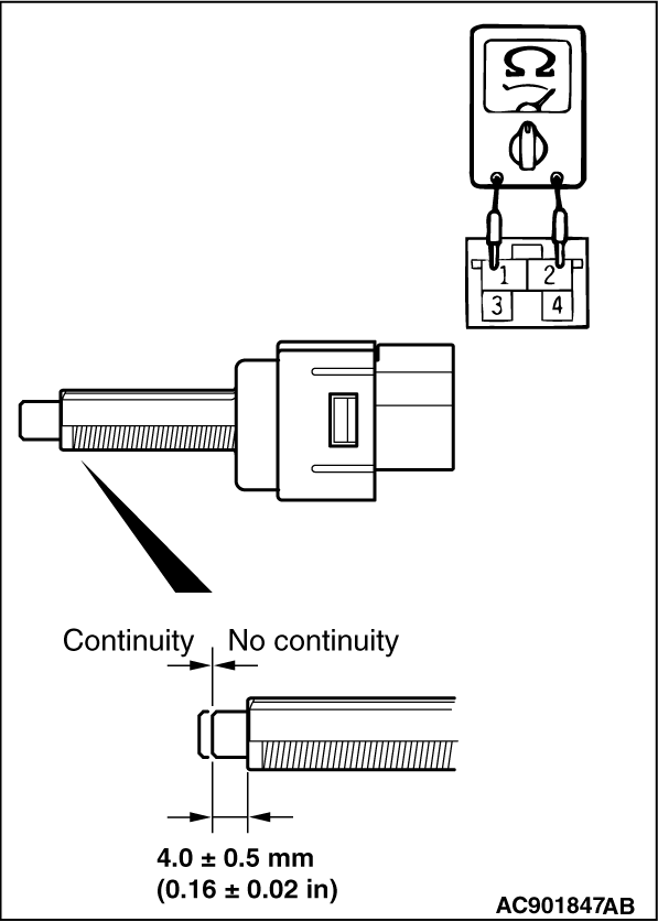
STEP 6. stop light switch continuity check
|
|
|
(1)Remove the stoplight switch (Refer to GROUP 35A -
Brake Pedal ).
|
|
(2)Connect the circuit tester (Ω
range) to the stoplight switch connector terminals
No.1 and 2.
(3)When no continuity is detected with the plunger pressed from the edge of the outer
case by the dimension shown in the figure and when continuity is detected with the plunger released,
the stoplight switch is in good condition.
Q.
Is the check result normal?
Go to Step 7.
Replace the stoplight switch. (Refer to GROUP 35A -
Brake Pedal .)
Then go to Step 22.
|
|
|
STEP 7. ETACS-ECU fuse No.2 check
|
|
|
Q.
Is the check result normal?
|
|
|
Go to Step 12.
|
|
|
|
|
|
Go to Step 8.
|
|
|
|
|
|
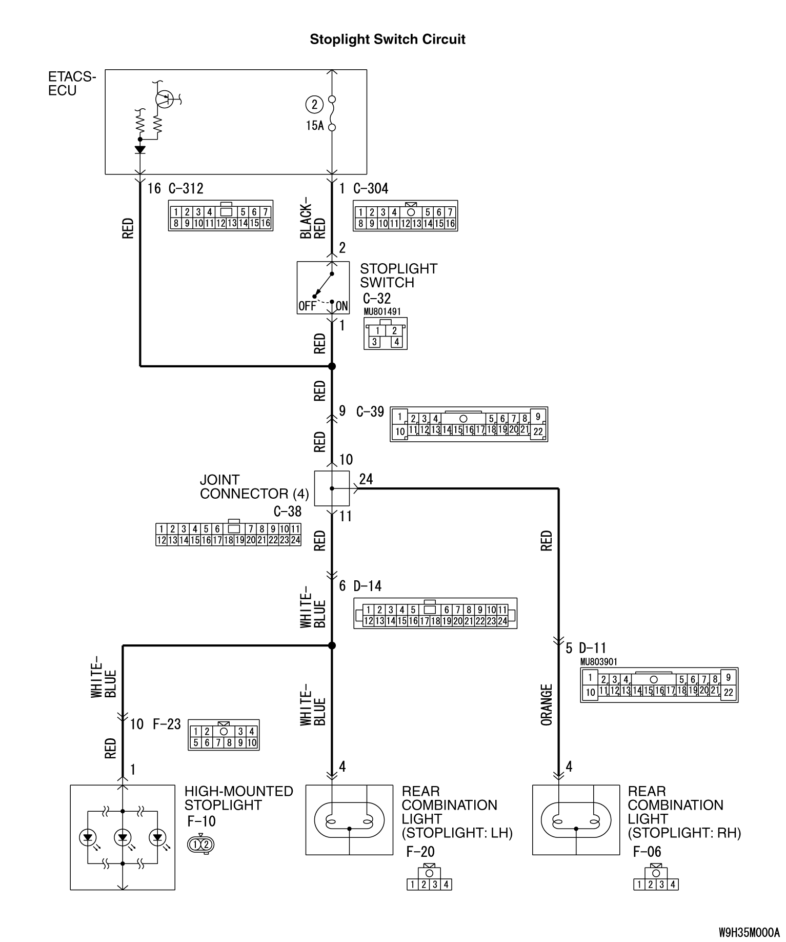
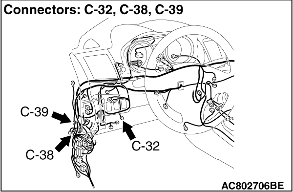
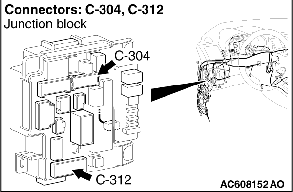
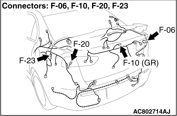
STEP 8. Connector check: C-304 ETACS-ECU connector, C-312 ETACS-ECU
connector, C-32 stoplight switch connector, C-39 Intermediate connector, C-38 joint connector,
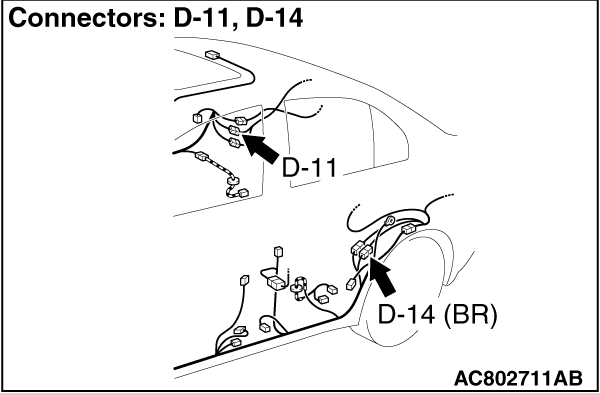
D-11 Intermediate connector, D-14 Intermediate connector, F-23 Intermediate connector, F-06
rear combination light (stoplight: RH) connector, F-20 rear combination light (stoplight: LH)
connector, F-10 high-mounted stoplight connector
|
|
|
Q.
Is the check result normal?
|
|
|
Go to Step 9.
|
|
|
|
|
|
Repair the damaged connector, and then replace fuse No.2. Then go to Step 22.
|
|
|
|
|
|
STEP 9. Resistance measurement at C-32 stoplight switch connector
|
|
|
(1)Disconnect C-32 stop light switch connector, and measure at the wiring harness
side.
|
|
|
(2)Disconnect C-312 ETACS-ECU connector and C-38 joint connector.
|
|
|
(3)Measure the resistance between the terminal No.1 and the body ground.
OK: No continuity
|
|
|
Q.
Is the check result normal?
|
|
|
Go to Step 10.
|
|
|
|
|
|
A short circuit may be present in the wiring harness between C-38 joint connector
terminal No.10 and C-32 stoplight switch connector terminal No.1 or between C-312 ETACS-ECU
connector terminal No.16 and C-32 stoplight switch connector terminal No.1. Repair the wiring
harness if necessary, and then replace fuse No.2. Then go to Step 22.
|
|
|
|
|
|
STEP 10. Resistance measurement at C-32 stop light switch connector
|
|
|
(1)Disconnect C-32 stop light switch connector, and measure at the wiring harness
side.
|
|
|
(2)Disconnect C-304 ETACS-ECU connector.
|
|
|
(3)Measure the resistance between the terminal No.2 and the body ground.
OK: No continuity
|
|
|
Q.
Is the check result normal?
|
|
|
Go to Step 11.
|
|
|
|
|
|
A short circuit may be present in the wiring harness between C-304 ETACS-ECU connector
terminal No.1 and C-32 stoplight switch connector terminal No.2. Repair the wiring harness if
necessary, and then replace fuse No.2. Then go to Step 22.
|
|
|
|
|
|
STEP 11. Resistance measurement at C-38 joint connector
|
|
|
(1)Disconnect C-38 joint connector, and measure at the wiring harness side.
|
|
|
(2)Disconnect F-06 rear combination light (stoplight: RH) connector, F-20 rear combination
light (stoplight: LH) connector, F-10 high-mounted stoplight connector.
|
|
|
(3)Measure the resistance between the terminal No.10 and the body ground.
OK: No continuity
|
|
|
Q.
Is the check result normal?
|
|
|
Replace fuse No.2. Then go to Step 21.
|
|
|
|
|
|
A short circuit may be present in the wiring harness between C-38 joint connector
terminal No.24 and F-06 rear combination light (stoplight: RH) connector terminal No.4 or between
C-38 joint connector terminal No.11 and F-20 rear combination light (stoplight: LH) connector
terminal No.4 or between C-38 joint connector terminal No.11 and F-10 high-mounted stoplight
connector terminal No.1. Repair the wiring harness if necessary, and then replace fuse No.2.
Then go to Step 22.
|
|
|
|
|
|
STEP 12. Connector check: C-304 ETACS-ECU connector
|
|
|
Q.
Is the check result normal?
|
|
|
Go to Step 13.
|
|
|
|
|
|
Repair the damaged connector.
|
|
|
|
|
|
STEP 13. Measure the voltage at the C-304 ETACS-ECU connector.
|
|
|
| caution |
Measure while the brake pedal is not depressed.
|
|
|
|
Measure the voltage between terminal No.1 and the body ground by backprobing.
|
|
|
OK: Battery positive voltage
|
|
|
Q.
Is the check result normal?
|
|
|
Go to Step 14.
|
|
|
|
|
|
Replace the ETACS-ECU (Refer to GROUP 54A -
ETACS-ECU ).
Then go to Step 22.
|
|
|
|
|
|
STEP 14. Connector check: C-32 Stoplight switch connector
|
|
|
Q.
Is the check result normal?
|
|
|
Go to Step 15.
|
|
|
|
|
|
Repair the damaged connector. Then go to Step 22.
|
|
|
|
|
|
STEP 15. Measure the voltage at C-32 stoplight switch connector.
|
|
|
(1)Disconnect C-32 stoplight switch connector, and measure the voltage at harness
connector side.
|
|
|
(2)Measure the voltage between the terminal No.2 and the body ground.
OK: Battery positive voltage
|
|
|
Q.
Is the check result normal?
|
|
|
Go to Step 16.
|
|
|
|
|
|
An open circuit may be present in the wiring harness between C-304 ETACS-ECU connector
terminal No. 1 and C-32 stoplight switch connector terminal No. 2. Repair the wiring harness.
Then go to Step 22.
|
|
|
|
|
|
STEP 16. Connector check: C-38 joint connector
|
|
|
Q.
Is the check result normal?
|
|
|
Go to Step 17.
|
|
|
|
|
|
Repair the damaged connector. Then go to Step 22.
|
|
|
|
|
|
STEP 17. Voltage measurement at C-38 joint connector
|
|
|
| caution |
Measure while the brake pedal is depressed.
|
|
|
|
(1)Disconnect the connector, and measure at the wiring harness side.
|
|
|
(2)Measure the voltage between the terminal No.10 and the body ground.
OK: Battery positive voltage
|
|
|
Q.
Is the check result normal?
|
|
|
Go to Step 18.
|
|
|
|
|
|
An open circuit may be present in the wiring harness between C-38 joint connector
terminal No.10 and C-32 stoplight switch connector terminal No.1. Repair the wiring harness.
|
|
|
|
|
|
STEP 18. Connector check: C-312 ETACS-ECU connector
|
|
|
Q.
Is the check result normal?
|
|
|
Go to Step 19.
|
|
|
|
|
|
Repair the damaged connector.
|
|
|
|
|
|
STEP 19. Measure the voltage at the C-312 ETACS-ECU connector.
|
|
|
(1)Measure by backprobing without disconnecting the connector.
|
|
|
(2)Measure the voltage between the terminal No.16 and the body earth.
OK:
When the brake pedal is released: 0 V - 5V (pulse)
When the brake pedal is depressed: Approximately battery positive voltage
|
|
|
Q.
Is the check result normal?
|
|
|
Go to Step 21.
|
|
|
|
|
|
Go to Step 20.
|
|
|
|
|
|
STEP 20. Check the wiring harness between C-312 ETACS-ECU connector
terminal No.16 and C-32 stoplight switch connector terminal No.1
|
|
|
- Check the signal line for open circuit.
|
|
|
Q.
Is the check result normal?
|
|
|
Replace the wiring harness.
|
|
|
|
|
|
STEP 21. Diagnostic trouble code recheck
|
|
|
Q.
Is diagnostic trouble code No.C1000 set?
|
|
|
Replace the hydraulic unit (ASC-ECU) (Refer to ). Then
go to Step 22.
|
|
|
|
|
|
Intermittent malfunction (Refer to GROUP 00 -
How to Cope with Intermittent
Malfunction .)
|
|
|
|
|
|
STEP 22. Diagnostic trouble code recheck
|
|
|
Q.
Is diagnostic trouble code No.C1000 set?
|
|
|
Return to Step 1.
|
|
|
|
|
|
This diagnosis is complete.
|
|
|
|
|
|
STEP 23. Diagnostic trouble code recheck
|
|
|
Q.
Is diagnostic trouble code No.C1000 set?
|
|
|
Replace the ETACS-ECU.
|
|
|
|
|
|
Intermittent malfunction (Refer to GROUP 00 -
How to Cope with Intermittent
Malfunction .)
|
|
|
|
)
)
)
)
)
)