![[Previous]](../../../buttons/fprev.png)
![[Next]](../../../buttons/fnext.png)
DTC C1032 Abnormality
in RR wheel speed sensor signal

|
|
| caution |
- If there is
any problem in the CAN bus lines, an incorrect DTC may be set. Prior to this diagnosis, diagnose
the CAN bus lines (Refer to GROUP 54C - CAN Bus Line Diagnostic Flow
 ). ).
- Whenever ECU is replaced, ensure that the CAN bus lines are normal.
- When the hydraulic unit (integrated with ASC-ECU) is replaced, always carry out
the calibration of the steering wheel sensor, the G and yaw rate sensor and brake fluid pressure
sensor (Refer to , and ).
|
|
|
|
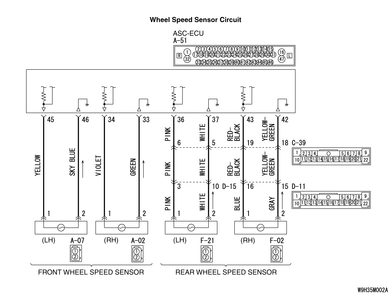
- Each wheel speed detecting section is a kind of a pulse generator. It consists
of the encoder (plate on which the north and south pole of magnet are arranged alternately)
for detecting the wheel speed, which rotates at the same speed of the wheels, and the wheel speed
sensor. This detecting section outputs the frequency pulse signals in proportion to the wheel speed.
- The pulse signals generated by the wheel speed detecting section are sent to ASC-ECU.
ASC-ECU uses the frequency of the pulse signals to determine the wheel speed.
|
|
|
ASC-ECU monitors the signals from each wheel speed sensor while the vehicle is being driven.
If any fault below is found in these sensor signals, ASC-ECU will set the relevant DTC.
|
|
|
- Irregular change in the wheel speed sensor signal
- Wheel speed sensor signal continuously indicates high value.
|
|
|
Current trouble
- Excessive gap between the wheel speed sensor and the wheel speed detection encoder
- Adhesion of foreign materials on the wheel speed sensor
- Adhesion of foreign materials on the wheel speed detection encoder
- Wheel bearing malfunction
- Malfunction of wheel speed sensor
- Damaged wiring harness and connectors
- External noise interference
- Improper installation of the wheel speed sensor
- Deformation of the wheel speed detection encoder
- ASC-ECU malfunction
- Disturbance of magnetization pattern for wheel speed detection encoder
- The number of poles on the Magnetic encoder for wheel speed detection (N-pole and
S-pole) is changed
|
|
|
Past trouble
- When DTC C102B is also set, carry out diagnosis with particular
emphasis on wiring harness and connector failures between ASC-ECU and the wheel speed sensor.
For diagnosis procedures, refer to How to treat past trouble (Refer to GROUP 00 - How
to Use Troubleshooting/How to Treat Past Trouble ).
- When DTC C102B is not set, the following conditions may be present:
- Some wheels slip
- Unstable vehicle attitude
- External noise interference
- Vehicle ran with the parking brake applied.
|
|
|
Required Special Tools:
- MB991958: Scan Tool (M.U.T.-III Sub Assembly)
- MB991824: Vehicle Communication Interface (V.C.I.)
- MB991827: M.U.T.-III USB Cable
- MB991910: M.U.T.-III Main Harness A
|
|
|
STEP 1. Using scan tool MB991958, diagnose the CAN bus
lines.
|
|
|
Use scan tool to diagnose the CAN bus lines.
|
|
|
Q.
Is the check result normal?
|
|
|
 Go to Step 3. Go to Step 3.
|
|
|
|
|
|
 Repair the CAN bus lines (Refer to GROUP 54C - CAN Bus Diagnostics Table ).
On completion, go to Step 2. Repair the CAN bus lines (Refer to GROUP 54C - CAN Bus Diagnostics Table ).
On completion, go to Step 2.
|
|
|
|
|
|
STEP 2. DTC recheck after resetting CAN bus lines
|
|
|
Go to Step 3.
|
|
|
|
|
|
The procedure is complete.
|
|
|
|
|
|
STEP 3. Using scan tool MB991958, check the DTC
|
|
|
Check that the DTC C102B is also set.
|
|
|
Q.
Is DTC C102B also set?
|
|
|
Perform the diagnosis for the DTC C102B (Refer to ).
|
|
|
|
|
|
Go to Step 4.
|
|
|
|
|
|
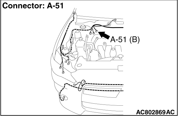
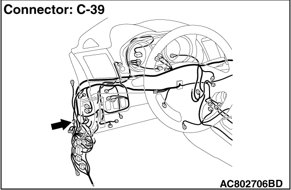
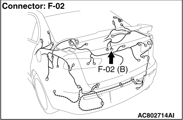
STEP 4. Connector check: A-51 ASC-ECU connector, C-39 intermediate
connector, D-11 intermediate connector, F-02 rear wheel speed sensor <RH> connector
|
|
|
Q.
Is the check result normal?
|
|
|
Go to Step 5.
|
|
|
|
|
|
Repair the defective connector. Then go to Step 12.
|
|
|
|
|
|
STEP 5. Wiring harness check between A-51 ASC-ECU connector terminal
No.43 and F-02 rear wheel speed sensor <RH> connector terminal No.1, and between
A-51 ASC-ECU connector terminal No.42 and F-02 rear wheel speed sensor <RH> connector
terminal No.2.
|
|
|
Q.
Is the check result normal?
|
|
|
Go to Step 6.
|
|
|
|
|
|
Repair the wiring harness. Then go to Step 12.
|
|
|
|
|
|
STEP 6. Check for wheel speed sensor <RR> installation
|
|
|
Check how the wheel speed sensor <RR> is installed (Disconnection of
wheel speed sensor <RR>, loose mounting bolt, etc.).
|
|
|
Q.
Is the check result normal?
|
|
|
Go to Step 7.
|
|
|
|
|
|
Reinstall the wheel speed sensor <RR> correctly (Refer to ).
Then go to Step 7.
|
|
|
|
|
|
STEP 7. Check for wheel speed sensor <RR> output
current
|
|
|
Refer to .
|
|
|
Q.
Is the check result normal?
|
|
|
Go to Step 8.
|
|
|
|
|
|
Replace the wheel speed sensor <RR> (Refer to ).
Then go to Step 11.
|
|
|
|
|
|
STEP 8. Check for wheel bearing looseness
|
|
|
| note |
- Loose wheel bearing may increase the gap between the wheel speed sensor <RR> and
the wheel speed detection magnet encoder.
- Check the Rear wheel hub assembly <RR (FWD)> (Refer to GROUP 27A - Wheel Bearing
Play Check ).
- Check the wheel bearing <RR (AWD)> for looseness (Refer to GROUP
27B - Wheel Bearing Play Check ).
|
|
|
|
Q.
Is the check result normal?
|
|
|
Go to Step 9.
|
|
|
|
|
|
NO (FWD) : Replace the rear wheel hub assembly <RR> (Refer to GROUP 27A - Rear
axle hub assembly ). Then go to Step 12. : Replace the rear wheel hub assembly <RR> (Refer to GROUP 27A - Rear
axle hub assembly ). Then go to Step 12.
|
|
|
|
|
|
NO (AWD) : Replace the wheel bearing <RR> (Refer to GROUP 27B - Rear
axle hub assembly ). Then go to Step 12.
|
|
|
|
|
|
STEP 9. Check of wheel speed detection encoder
|
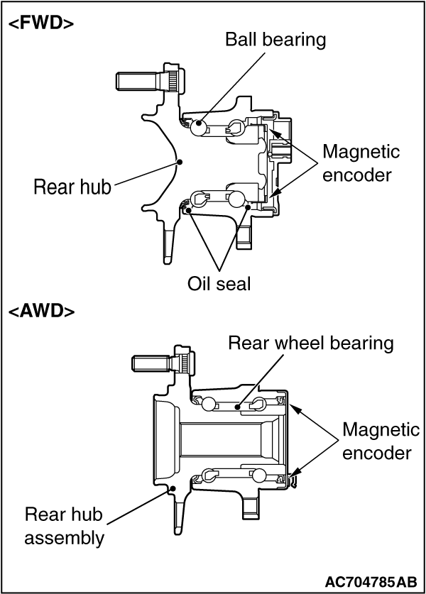
|
Check the encoder for adhesion of foreign materials or deformation.
Q.
Is the check result normal?
Go to Step 10.
NO (Adhesion of foreign materials) : Remove the foreign materials and clean the encoder so as not to disturb the magnetization
pattern on it while taking care of the magnet, magnetic substance, and magnetic attraction.
Then go to Step 12.
NO <Deformation (FWD)> : Replace the rear wheel hub assembly <RR> (Refer to GROUP 27A - Rear
axle hub assembly ). Then go to Step 12.
NO <Deformation (AWD)> : Replace the wheel bearing <RR> (Refer to GROUP 27B - Rear
axle hub assembly ). Then go to Step 12.
|
|
|
STEP 10. Check whether the DTC is reset.
|
|
|
(2)Drive the vehicle at 12mph (20 km/h) or higher.
| note |
The ABS warning light does not turn OFF in some cases unless the vehicle runs at 12mph
(20 km/h) or higher.
|
|
|
|
Replace the wheel speed sensor <RR> (Refer to ). Then
go to Step 11.
|
|
|
|
|
|
Intermittent malfunction (Refer to GROUP 00 - How to Use Troubleshooting/How
to Cope with Intermittent Malfunctions ).
|
|
|
|
|
|
STEP 11. Check whether the DTC is reset.
|
|
|
(2)Drive the vehicle at 12 mph (20 km/h) or higher.
| note |
The ABS warning light does not turn OFF in some cases unless the vehicle runs at 12 mph
(20 km/h) or higher.
|
|
|
|
Replace the hydraulic unit (integrated with ASC-ECU) (Refer to ).
Then go to Step 12.
|
|
|
|
|
|
The procedure is complete.
|
|
|
|
|
|
STEP 12. Check whether the DTC is reset.
|
|
|
(2)Drive the vehicle at 12 mph (20 km/h) or higher.
| note |
The ABS warning light does not turn OFF in some cases unless the vehicle runs at 12 mph
(20 km/h) or higher.
|
|
|
|
Return to Step 1.
|
|
|
|
|
|
The procedure is complete.
|
|
|
|
)
)
)
)
)
)