|
|
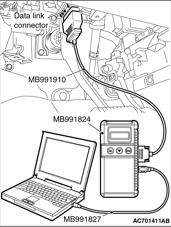
Required Special Tools:
- MB991958: Scan Tool (M.U.T.-III Sub Assembly)
- MB991824: Vehicle Communication Interface (V.C.I.)
- MB991827: M.U.T.-III USB Cable
- MB991910: M.U.T.-III Main Harness A
|
|
| caution |
To prevent damage to scan tool MB991958, always turn the ignition switch to the "LOCK" (OFF) position before connecting or disconnecting scan tool MB991958.
|
1.Ensure that the ignition switch is at the "LOCK" (OFF) position.
2.Start up the personal computer.
3.Connect special tool MB991827 to special tool MB991824 and the personal computer.
4.Connect special tool MB991910 to the special tool MB991824.
5.Connect special tool MB991910 to the data link connector.
6.Turn the power switch special tool MB991824 to the "ON" position.
| note |
When the special tool MB991824 is energized, the special tool MB991824 indicator light will be illuminated in a green color.
|
7.Start the M.U.T.-III system on the personal computer.
| note |
Disconnect the scan tool MB991958 in the reverse order of the connecting sequence, making sure that the ignition switch is at the "LOCK" (OFF) position.
|
|
|
|
Required Special Tools:
- MB991958: Scan Tool (M.U.T.-III Sub Assembly)
- MB991824: Vehicle Communication Interface (V.C.I.)
- MB991827: M.U.T.-III USB Cable
- MB991910: M.U.T.-III Main Harness A
|
|
| caution |
To prevent damage to scan tool MB991958, always turn the ignition switch to the "LOCK" (OFF) position before connecting or disconnecting scan tool MB991958.
|
| note |
If the battery voltage is low, diagnostic trouble codes will not be set. Check the battery if scan tool MB991958 does not display.
|
1.Connect scan tool MB991958 to the data link connector.
2.Turn the ignition switch to the "ON" position.
3.Select "System Select."
4.Select "ABS/ASC/ASTC" from the system list, and select the "OK" button.
5.Select "Diagnostic Trouble Code." to read the DTC.
6.If a DTC is set, it is shown.
7.Choose "DTC erase" to erase the DTC.
|
|
|
Required Special Tools:
- MB991958: Scan Tool (M.U.T.-III Sub Assembly)
- MB991824: Vehicle Communication Interface (V.C.I.)
- MB991827: M.U.T.-III USB Cable
- MB991910: M.U.T.-III Main Harness A
|
|
| caution |
To prevent damage to scan tool MB991958, always turn the ignition switch to the "LOCK" (OFF) position before connecting or disconnecting scan tool MB991958.
|
1.Connect scan tool MB991958 to the data link connector.
2.Turn the ignition switch to the "ON" position.
3.Select "System Select."
4.Select "ABS/ASC/ASTC" from the system list, and select the "OK" button.
5.Select "Data List."
|
|
|
Required Special Tools:
- MB991958: Scan Tool (M.U.T.-III Sub Assembly)
- MB991824: Vehicle Communication Interface (V.C.I.)
- MB991827: M.U.T.-III USB Cable
- MB991910: M.U.T.-III Main Harness A
|
|
| caution |
To prevent damage to scan tool MB991958, always turn the ignition switch to the "LOCK" (OFF) position before connecting or disconnecting scan tool MB991958.
|
1.Connect scan tool MB991958 to the data link connector.
2.Turn the ignition switch to the "ON" position.
3.Select "System Select."
4.Select "ABS/ASC/ASTC" from the system list, and select the "OK" button.
5.Choose "Actuator Test" from "ABS" screen.
6.Choose an appropriate item and select the "OK" button.
|
|
|
Required Special Tools:
- MB991958: Scan Tool (M.U.T.-III Sub Assembly)
- MB991824: Vehicle Communication Interface (V.C.I.)
- MB991827: M.U.T.-III USB Cable
- MB991910: M.U.T.-III Main Harness A
|
|
| caution |
To prevent damage to scan tool MB991958, always turn the ignition switch to the "LOCK" (OFF) position before connecting or disconnecting scan tool MB991958.
|
1.Connect scan tool MB991958 to the data link connector.
2.Turn the ignition switch to the "ON" position.
3.Select "CAN bus diagnosis" from the start-up screen.
4.When the vehicle information is displayed, confirm that it matches the vehicle whose CAN bus lines will be diagnosed.
- If they match, go to step 8.
- If not, go to step 5.
5.Select "view vehicle information" button.
6.When the vehicle information is displayed, confirm again that it matches the vehicle which is being diagnosed.
- If they match, go to step 8.
- If not, go to step 5.
7.Press the "OK" button.
8.When the options are displayed, choose the options (mark the check) and then select "OK".
|
![[Previous]](../../../buttons/fprev.png)
![[Next]](../../../buttons/fnext.png)
)