|
|
Measure wheel alignment with alignment equipment on a level surface. The front suspension, steering system, wheels, and tires should be serviced to normal condition before measuring wheel alignment.
|
|
|
Standard value: 1 ± 2 mm (0.04 ± 0.08 inch)
|

|
1.Adjust the toe-in by undoing the bellows clip and lock nut, and turning the left and right tie rod turnbuckles by the same amount (in opposite directions).
| note |
The toe will move out as the left turnbuckle is turned toward the front of the vehicle and the right turnbuckle is turned toward the rear of the vehicle.
|
2.Install the bellows clip and tighten the lock nut to the specified torque.
Tightening torque: 52 ± 2 N·m (38 ± 1 ft-lb)
3.Confirm that the toe-in is at the standard value.
4.Use a turning radius gauge to check that the steering angle is at the standard value.
Standard value:
|
|
Inner wheel
|
40°50’ ± 1°30’
|
Outer wheel
(reference value)
|
33°50’
|
|
|
|
|
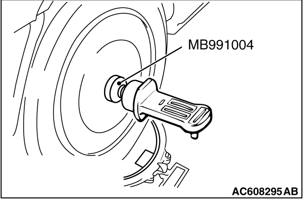
Required Special Tool:
- MB991004: Wheel Alignment Gauge Attachment
<Vehicles with aluminum wheels>
|
|
|
Standard value:
Camber - 0°05’ ± 0°30’ (Left/right deviation within 30’)
Caster 2°40’ ± 0°30’ (Left/right deviation within 30’)
Kingpin inclination 13°30’ ± 1°30’
|
|
| note |
For vehicles with aluminum type wheels, attach the camber/caster/kingpin gauge to the driveshaft by using the special tool MB991004. Tighten the special tool MB991004 to the same torque 144 - 176 N·m (106 - 130 ft-lb) as the driveshaft nut.
|
|
![[Previous]](../../../buttons/fprev.png)
![[Next]](../../../buttons/fnext.png)
)
)
