[Previous] [Next]

REMOVAL AND INSTALLATION


Pre-removal and Post-installation operation
  • Engine Room Under Cover Front A, Engine Room Under Cover Center, Engine Room Under Cover Front B Removal and Installation (Refer to GROUP 51, Under Cover .)
  • Transfer Oil Draining and Filling (Refer to GROUP 22C, On-vehicle Service, Transfer Oil Change .)


Removal steps


1.
Heat protector
<<A>>
>>B<<
2.
Propeller shaft flange yoke and rear differential connection nut


3.
Bolt


4.
Insulator


5.
Spacer
<<B>>
>>A<<
6.
Propeller shaft assembly

REMOVAL SERVICE POINTS


<<A>> PROPELLER SHAFT FLANGE YOKE AND REAR DIFFERENTIAL CONNECTION NUT


Put mating marks on the flange yoke and the differential companion flange and remove the connecting nuts.

<<B>> PROPELLER SHAFT ASSEMBLY REMOVAL


caution If the joint assembly is bent, it may be damaged when pinching the joint boots.

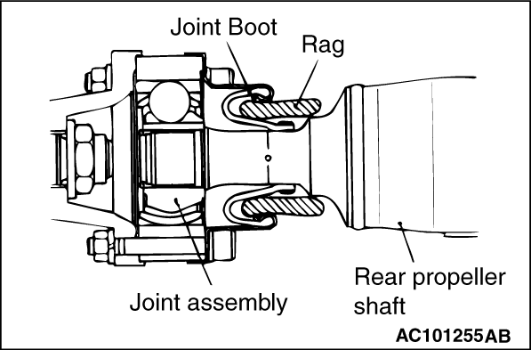
Insert a rag or similar materials into the joint boots, and remove the propeller shaft assembly by aligning the front propeller shaft with the rear shaft.

INSTALLATION SERVICE POINTS


>>A<< PROPELLER SHAFT ASSEMBLY INSTALLATION


caution
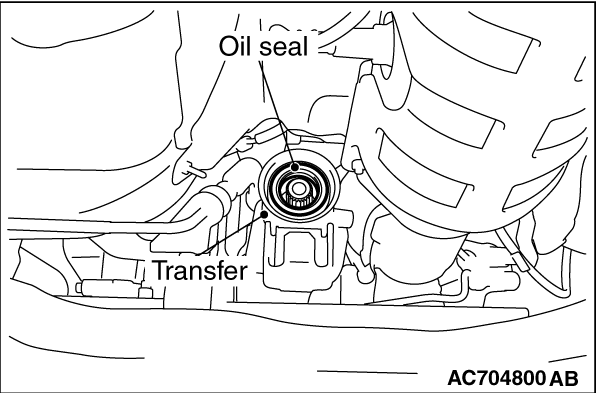
  • Do not damage the oil seal lip of the transfer.
  • The mounting bolt and nut may be loosened if oil or grease is stuck on the threads of the bolt and nut. Tighten them after degreasing the threads.
  • If the joint assembly is bent, it may be damaged when pinching the joint boots.

>>B<< PROPELLER SHAFT FLANGE YOKE AND REAR DIFFERENTIAL CONNECTION NUT INSTALLATION


If the propeller shaft is reused, align the mating marks and install the connecting nuts.
Tightening torque: 54 ± 5 N·m (40 ± 3 ft-lb)