|
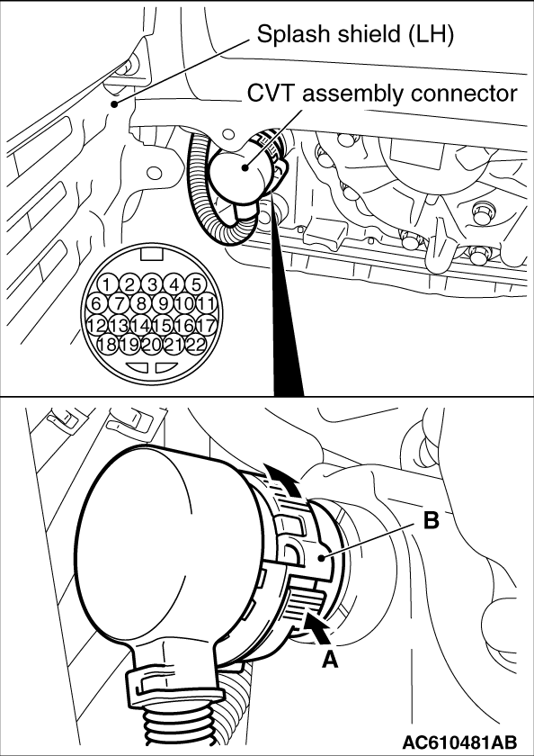
1.While pressing A in the figure, turn B counterclockwise to unlock the CVT assembly connector, and disconnect the connector.
2.Measure the resistance between the terminals of the applicable solenoid valves and ground.
Standard value:
|
|
Terminal No.
|
Applicable solenoid valve
|
Resistance value Ω
|
1
|
Line pressure solenoid valve
|
Approximately 5.6 to 6.6
|
2
|
Secondary pressure solenoid valve
|
3
|
Lockup solenoid valve
|
4
|
Lockup/select switching solenoid valve
|
Approximately 25.5 to 29.3
|
|
3.When the resistance is within the standard value, check the power supply and the ground circuits.
4.
| caution |
Each solenoid valve cannot be removed or replaced as a single unit. When replacement of any one of the solenoid valves is necessary, replace the valve body assembly.
|
When the resistance is outside the standard value, replace the valve body assembly and the harness.
|
![[Previous]](../../../buttons/fprev.png)
![[Next]](../../../buttons/fnext.png)
)