|
|
Item 5: Transmission fluid temperature sensor signal (Refer to Data List Reference Table  ). ).
|
|
|
Q.
Is the check result normal?
|
|
|
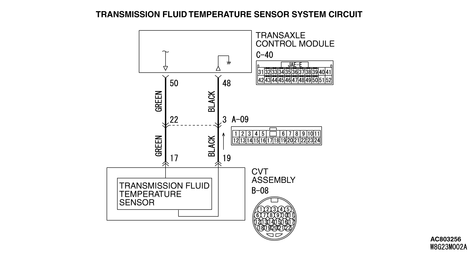
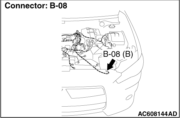
- B-08 Transmission assembly connector
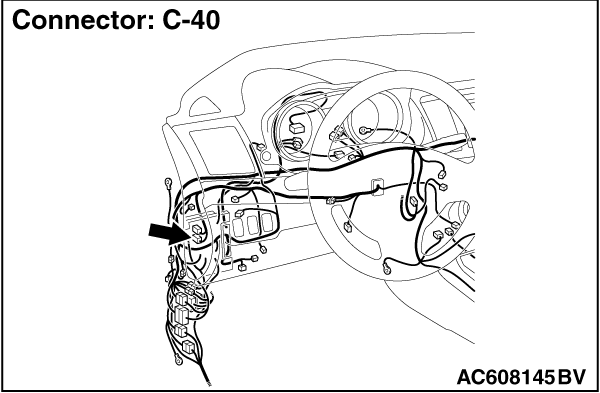
- C-40 TCM connector
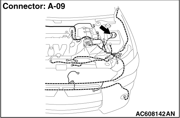
- A-09 Intermediate connector
|
|
|
Check the terminals for a contact status problem and internal short circuit.
|
|
|
Q.
Is the check result normal?
|
|
|
 Repair the defective connector. Repair the defective connector.
|
|
|
|
|
|
Between B-08 CVT assembly connector (terminal No.17) and C-40 TCM connector (terminal No.50)
|
|
|
Q.
Is the check result normal?
|
|
|
 Repair the wiring harness. Repair the wiring harness.
|
|
|
|
|
|
Between B-08 CVT assembly connector (terminal No.19) and C-40 TCM connector (terminal No.48)
|
|
|
Q.
Is the check result normal?
|
|
|
 Repair the wiring harness. Repair the wiring harness.
|
|
|
|
|
|
Q.
Is the check result normal?
|
|
|
 Replace the valve body assembly. Replace the valve body assembly.
|
|
|
|
|
|
Q.
Is the check result normal?
|
 ).
).![[Previous]](../../../buttons/fprev.png)
![[Next]](../../../buttons/fnext.png)
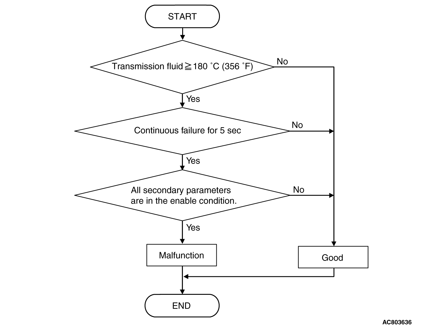
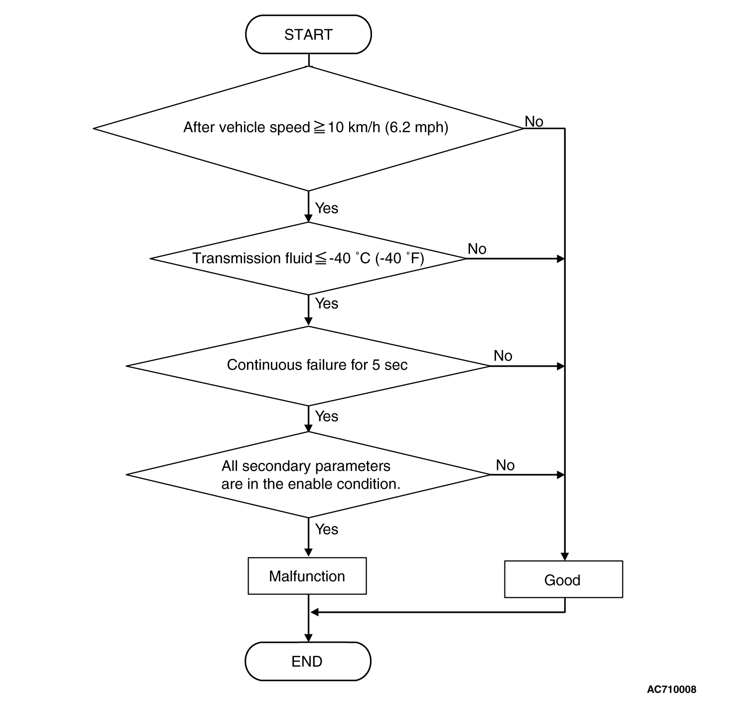
 ).
). Intermittent malfunction
 Go to Step 2.
 Go to Step 3.
 Repair the defective connector.
 Go to Step 4.
 Repair the wiring harness.
 Go to Step 5.
 Repair the wiring harness.
 .
. Go to Step 6.
 Replace the valve body assembly.
 Intermittent malfunction
 Replace TCM.