![[Previous]](../../../buttons/fprev.png)
![[Next]](../../../buttons/fnext.png)
DTC P1836: Shift
Fork 1 Malfunction
| caution |
- If there is any problem in the
CAN bus lines, an incorrect diagnostic trouble code may be set. Prior to this diagnosis, diagnose
the CAN bus lines.
- Whenever the ECU is replaced, ensure that the CAN bus lines are normal.
|
DIAGNOSTIC FUNCTION
TC-SST-ECU checks that the movement of the shift fork 1 is normal.
DESCRIPTIONS OF MONITOR METHODS
The movement of the shift fork 1 is determined to be abnormal.
MONITOR EXECUTION
MONITOR EXECUTION CONDITIONS (OTHER MONITOR AND SENSOR)
Other Monitor (There is no temporary DTC stored in memory
for the item monitored below)
- P183D: Shift fork 2 malfunction
- P1844: Shift fork 3 malfunction
Sensor (The sensor below is determined to be normal)
LOGIC FLOW CHARTS (Monitor Sequence) <Functional check - blocked>
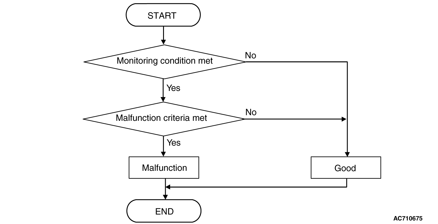
DTC SET CONDITIONS <FUNCTIONAL CHECK - BLOCKED>
Check Conditions
- Voltage of battery: 8 V or more.
- Voltage of battery: 16.5 V or less.
- Engine speed: 650 r/min or more.
- Time since above engine condition: 1.5 second or more.
- Common high side 1 voltage: 2.5 V or more.
- Common high side 3 voltage: 2.5 V or more.
JUDGMENT CRITERIA
- Shift fork operation time: Shift fork operation time (threshold value) or more.
(immediately)
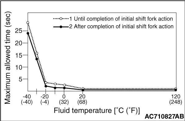
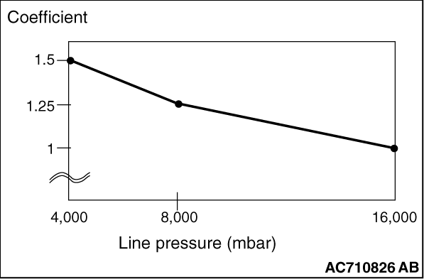
- Shift fork operation time (threshold value): Equal the maximum allowed time x Coefficient. (immediately)
OBD-II DRIVE CYCLE PATTERN <FUNCTIONAL CHECK - BLOCKED>
The shift fork operation time is threshold value or less.
LOGIC FLOW CHARTS (Monitor Sequence) <Functional check - Neutral>
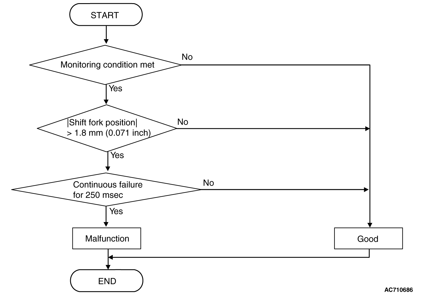
DTC SET CONDITIONS <FUNCTIONAL CHECK - NEUTRAL>
Check Conditions
- Voltage of battery: 8 V or more.
- Voltage of battery: 16.5 V or less.
- Engine speed: 650 r/min or more.
- Time since above engine condition: 1.5 second or more.
- Shift fork 1 current gear: Neutral.
JUDGMENT CRITERIA
- Shift fork position: 1.8 mm (0.071 inch) or more. (250 millisecond)
OBD-II DRIVE CYCLE PATTERN <FUNCTIONAL CHECK - NEUTRAL>
The shift fork position remains 1.8 mm (0.071 inch) or less for 250 milliseconds.
LOGIC FLOW CHARTS (Monitor Sequence) <Functional check - Shift
fork 1 requested but shift fork 3 movement>
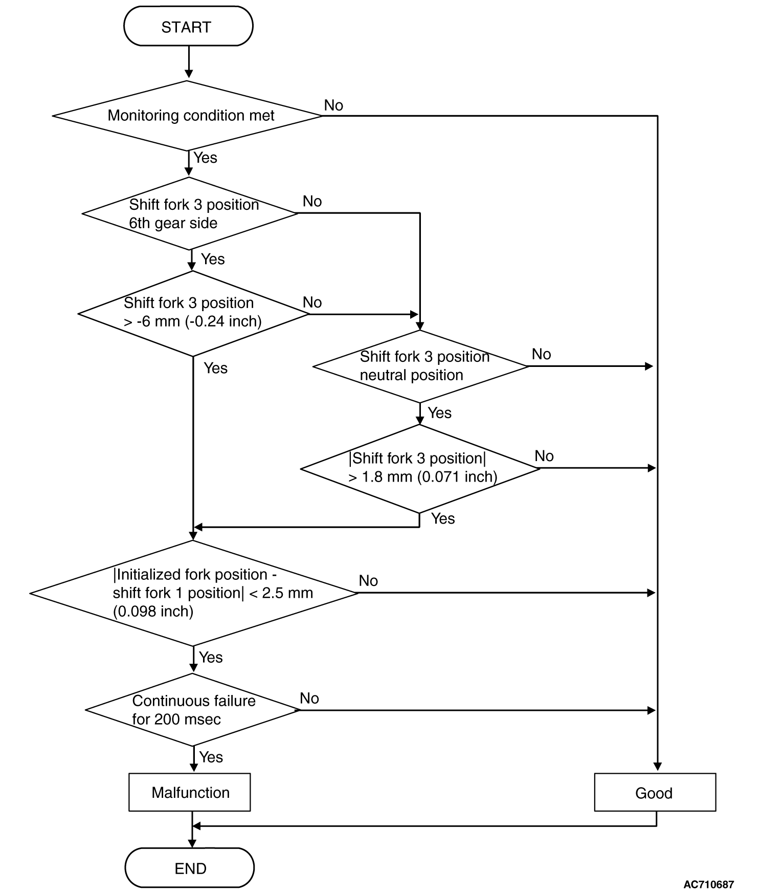
DTC SET CONDITIONS <FUNCTIONAL CHECK - SHIFT FORK 1 REQUESTED BUT SHIFT FORK
3 MOVEMENT>
Check Conditions
- Voltage of battery: 8 V or more.
- Voltage of battery: 16.5 V or less.
- Engine speed: 650 r/min or more.
- Time since above engine condition: 1.5 second or more.
- Requested shift fork: Shift fork 1.
JUDGMENT CRITERIA
- Shift fork 3 position: -6 mm (-0.24 inch) [6th gear side] or
more, or 1.8 mm (0.071 inch) [neutral position] or more, and initialized fork
position - shift fork 1 position: 2.5 mm (0.098 inch) or less. (200 millisecond)
OBD-II DRIVE CYCLE PATTERN <FUNCTIONAL CHECK - SHIFT FORK 1 REQUESTED BUT SHIFT
FORK 3 MOVEMENT>
The status with the shift fork position -6 mm (-0.24 inch) [6th
gear side] or less, or with 1.8 mm (0.071 inch) [neutral position] or
less and with the initialized fork position - shift fork 1 position 2.5 mm (0.098 inch)
or more continues for 200 milliseconds.
LOGIC FLOW CHARTS (Monitor Sequence) <Functional check - Shift
fork 1 requested but shift fork 2 movement>
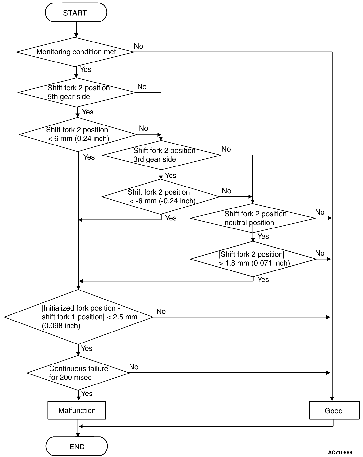
DTC SET CONDITIONS <FUNCTIONAL CHECK - SHIFT FORK 1 REQUESTED BUT SHIFT FORK
2 MOVEMENT>
Check Conditions
- Voltage of battery: 8 V or more.
- Voltage of battery: 16.5 V or less.
- Engine speed: 650 r/min or more.
- Time since above engine condition: 1.5 second or more.
- Requested shift fork: Shift fork 1.
JUDGMENT CRITERIA
- Shift fork position: 6 mm (0.24 inch) [5th gear side] or less,
or -6 mm (-0.24 inch) [3rd gear side] or more, or 1.8 mm
(0.071 inch) [neutral position] or more, and initialized fork position - shift
fork 1 position: 2.5 mm (0.098 inch) or less. (200 millisecond)
OBD-II DRIVE CYCLE PATTERN <FUNCTIONAL CHECK - SHIFT FORK 1 REQUESTED BUT SHIFT
FORK 2 MOVEMENT>
The status with the shift fork position 6 mm (0.24 inch) [5th gear side] or
more, or with -6 mm (-0.24 inch) [3rd gear side] or less,
or with 1.8 mm (0.071 inch) [neutral position] or less and with the initialized
fork position - shift fork 1 position 2.5 mm (0.098 inch) or more continues for 200
milliseconds.
PROBABLE CAUSES
- Malfunction of TC-SST-ECU
- Malfunction of TC-SST shift fork
|
|
Required Special Tools:
- MB991958 Scan Tool (M.U.T.-III Sub Assembly)
- MB991824: Vehicle Communication Interface (V.C.I.)
- MB991827 M.U.T.-III USB Cable
- MB991910 M.U.T.-III Main Harness A
|
|
|
STEP 1. Scan tool CAN bus diagnostics
|
|
|
Using scan tool MB991958, diagnose the CAN bus lines.
|
|
|
Q.
Is the check result normal?
|
|
|
 Go to Step 2. Go to Step 2.
|
|
|
|
|
|
 Repair the CAN bus lines. (Refer to GROUP 54C - Troubleshooting Repair the CAN bus lines. (Refer to GROUP 54C - Troubleshooting  .)
After repairing the CAN bus line, go to Step 2. .)
After repairing the CAN bus line, go to Step 2.
|
|
|
|
|
|
STEP 2. Monitoring unit No. check
|
|
|
(1)Check the freeze frame data (item No. 30 to No. 37).
|
|
|
(2)Check which monitoring unit (No. 160, No. 172, No. 182, or No. 183) is set.
|
|
|
Q.
Which monitoring unit is set, No. 160, No. 172, No. 182, or No. 183?
|
|
|
No. 160 : Go to Step 4 : Go to Step 4
|
|
|
|
|
|
Other than No. 160 : Go to Step 3
|
|
|
|
|
|
STEP 3. Check whether the DTC is reset.
|
|
|
(2)Drive with shifting to each gear range.
|
|
|
(3)Check that the DTC is reset.
|
|
|
Replace the transaxle assembly. (Refer to .)
|
|
|
|
|
|
Intermittent malfunction. (Refer to GROUP 00 - How to Cope with Intermittent
Malfunction .)
|
|
|
|
|
|
STEP 4. Check whether the DTC is reset.
|
|
|
(2)With the engine idle status, operate the shift lever in the following sequence:
P → R → D → R → P. (Hold each range for 5 seconds or more.)
|
|
|
(3)Check that the DTC is reset.
|
|
|
Replace the transaxle assembly. (Refer to .)
|
|
|
|
|
|
Intermittent malfunction. (Refer to GROUP 00 - How to Cope with Intermittent
Malfunction .)
|
|
|
|
)
)
)
)
)
)