![[Previous]](../../../buttons/fprev.png)
![[Next]](../../../buttons/fnext.png)
DTC P0716: Input
shaft 1 (odd number gear axle) speed sensor system (Poor performance)
| caution |
- If there is any problem in the
CAN bus lines, an incorrect diagnostic trouble code may be set. Prior to this diagnosis, diagnose
the CAN bus lines.
- Whenever the ECU is replaced, ensure that the CAN bus lines are normal.
|
DIAGNOSTIC FUNCTION
TC-SST-ECU checks that the input shaft 1 (odd number gear axle) speed sensor is normal.
DESCRIPTIONS OF MONITOR METHODS
The rotation speed of the input shaft 1 (odd number gear axle) is determined to be abnormal.
MONITOR EXECUTION
MONITOR EXECUTION CONDITIONS (OTHER MONITOR AND SENSOR)
Other Monitor (There is no temporary DTC stored in memory
for the item monitored below)
- P0715: Input shaft 1 (odd number gear axle) speed sensor system (Output high range
out)
- P0717: Input shaft 1 (odd number gear axle) speed sensor system (Output low range
out)
- P2766: Input shaft 2 (even number gear axle) speed sensor system (Poor performance)
Sensor (The sensor below is determined to be normal)
- Input shaft 2 (even number gear axle) speed sensor
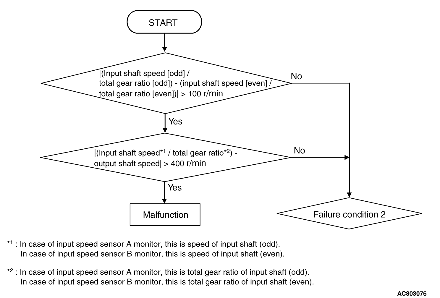
LOGIC FLOW CHARTS (Monitor Sequence) <Rationality>

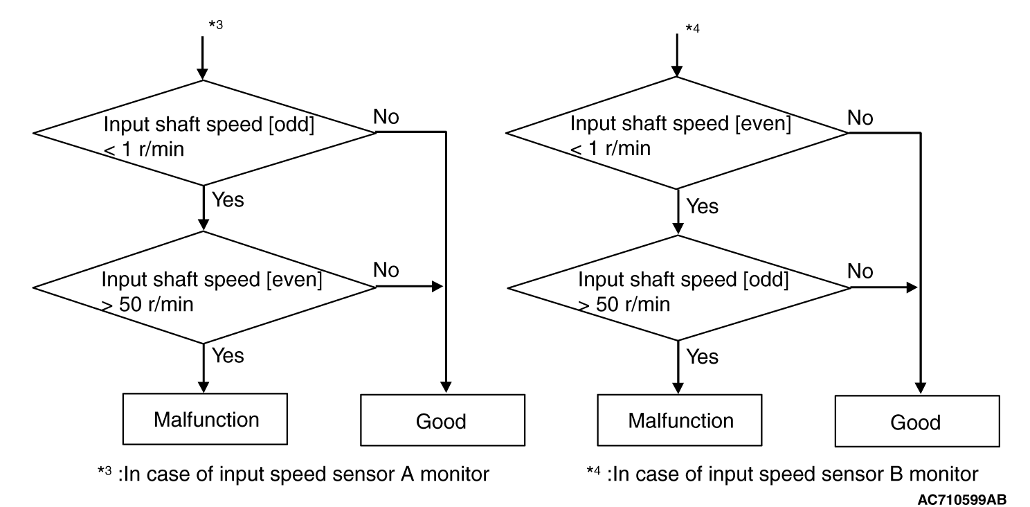
LOGIC FLOW CHARTS (Monitor Sequence) <Rationality (Failure
condition 1)>
LOGIC FLOW CHARTS (Monitor Sequence) <Rationality (Failure
condition 2)>
DTC SET CONDITIONS
Check Conditions <Rationality>
- Voltage of battery: 8 V or more.
- Voltage of battery: 16.5 V or less.
- Input shaft [odd] gear: engaged.
- Input shaft [even] gear: engaged.
JUDGMENT CRITERIA <Rationality>
- Failure condition 1 or failure condition 2 (Refer to Logic Flow Charts (Monitor
Sequence) <Rationality>). (500 millisecond)
OBD-II DRIVE CYCLE PATTERN <RATIONALITY>
Each value of failure condition 1 or failure condition 2 (Logic Flow Charts (Monitor Sequence) <Rationality>)
returns to the normal value and remains in the state for 500 milliseconds.
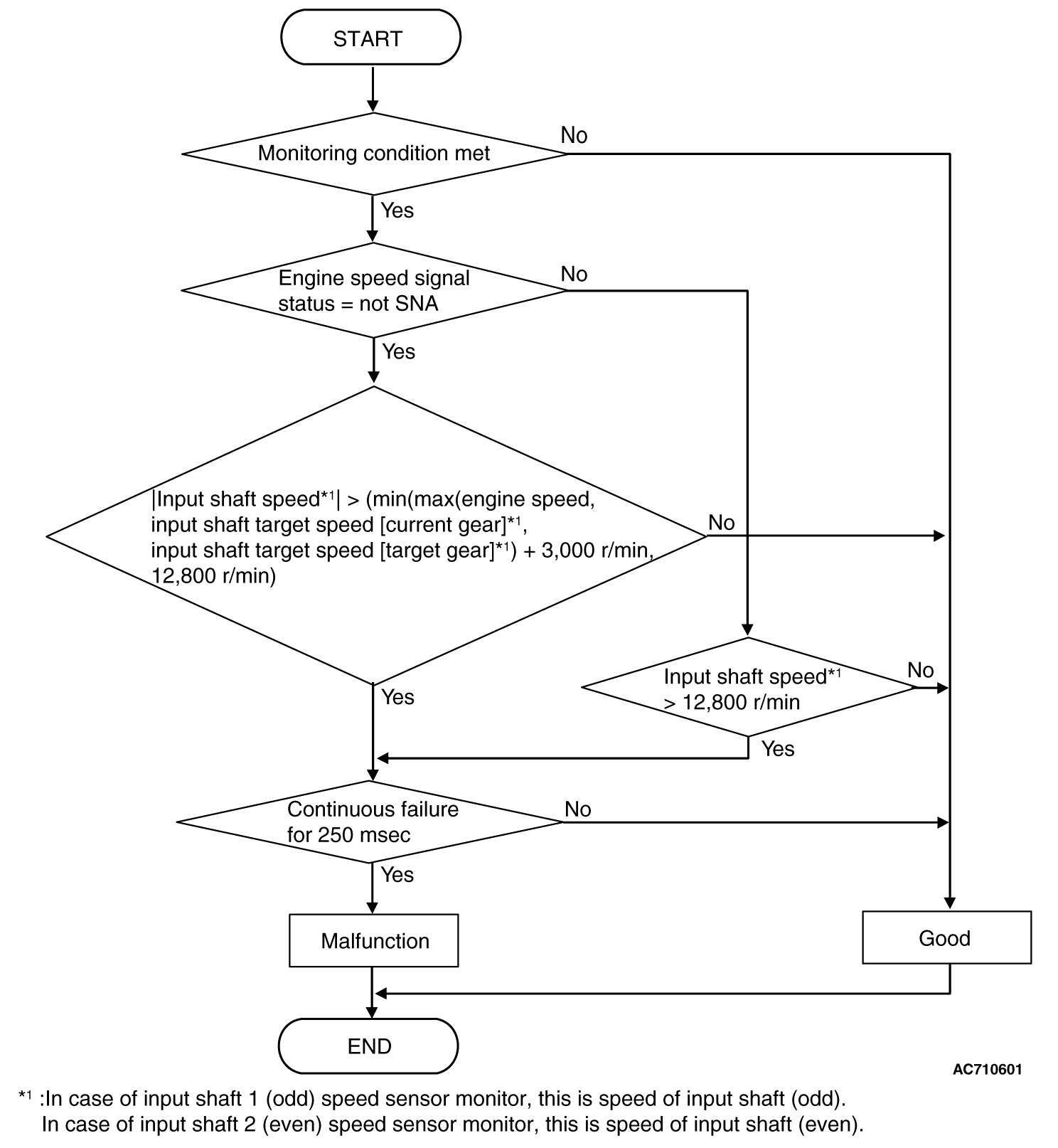
LOGIC FLOW CHARTS (Monitor Sequence) <Rationality - plausibility
failure>
Check Conditions <Rationality plausibility failure>
- Voltage of battery: 8 V or more.
- Voltage of battery: 16.5 V or less.
JUDGMENT CRITERIA <Rationality plausibility failure>
- Input shaft 1 (odd) speed: Refer to Logic Flow Charts (Monitor Sequence) <Rationality plausibility
failure>. (250 millisecond)
OBD-II DRIVE CYCLE PATTERN <RATIONALITY PLAUSIBILITY FAILURE>
The value of the Logic Flow Charts (Monitor Sequence) <Rationality plausibility
failure> returns to the normal value and remains in the state for 250 milliseconds.
PROBABLE CAUSES
- Malfunction of TC-SST-ECU
- Malfunction of input shaft 1 speed sensor
|
|
Required Special Tools:
- MB991958 Scan Tool (M.U.T.-III Sub Assembly)
- MB991824: Vehicle Communication Interface (V.C.I.)
- MB991827 M.U.T.-III USB Cable
- MB991910 M.U.T.-III Main Harness A
|
|
|
STEP 1. Scan tool CAN bus diagnostics
|
|
|
Using scan tool MB991958, diagnose the CAN bus lines.
|
|
|
Q.
Is the check result normal?
|
|
|
 Go to Step 2. Go to Step 2.
|
|
|
|
|
|
 Repair the CAN bus lines. (Refer to GROUP 54C - Troubleshooting Repair the CAN bus lines. (Refer to GROUP 54C - Troubleshooting  .)
After repairing the CAN bus line, go to Step 2. .)
After repairing the CAN bus line, go to Step 2.
|
|
|
|
|
|
STEP 2. Monitoring unit No. check
|
|
|
(1)Check the freeze frame data (item No. 30 to No. 37).
|
|
|
(2)Check which monitoring unit (No. 114 or No. 138) is set.
|
|
|
Q.
Which monitoring unit is set, No. 114 or No. 138?
|
|
|
No. 114 : Go to Step 4 : Go to Step 4
|
|
|
|
|
|
No. 138 : Go to Step 3
|
|
|
|
|
|
STEP 3. Check whether the DTC is reset.
|
|
|
(2)Drive the vehicle at 50 km/h (31 mph) or more.
|
|
|
(3)Check that the DTC is reset.
|
|
|
Replace the transaxle assembly. (Refer to .)
|
|
|
|
|
|
Intermittent malfunction. (Refer to GROUP 00 - How to Cope with Intermittent
Malfunction .)
|
|
|
|
|
|
STEP 4. Check whether the DTC is reset.
|
|
|
(2)
| caution |
When driving with each gear range, check that the
gear engagement is correct and the engine rotation speed does not increase abnormally after
gear shifting.
|
Drive with shifting to each gear range.
|
|
|
(3)Check that the DTC is reset.
|
|
|
Replace the transaxle assembly. (Refer to .)
|
|
|
|
|
|
Intermittent malfunction. (Refer to GROUP 00 - How to Cope with Intermittent
Malfunction .)
|
|
|
|
)
)
)
)