|
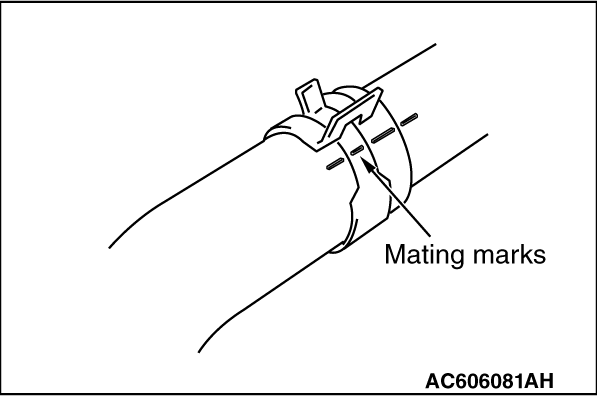
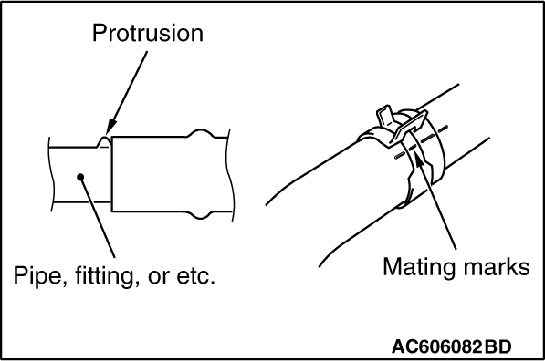
Make mating marks on the radiator upper hose and the hose clamp as shown to install them
in the original position. Then, remove them.
|
|
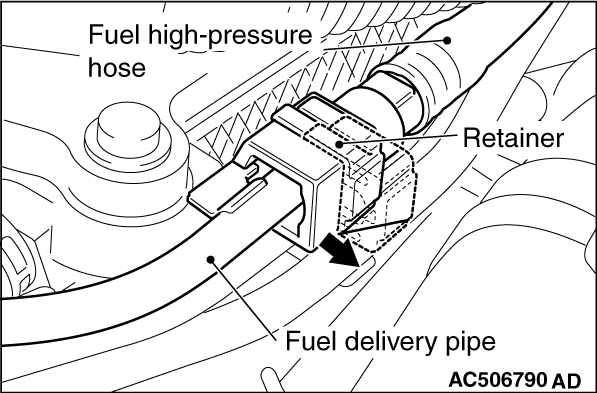
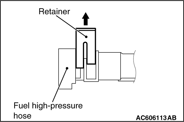
1.Follow the steps below to unlock the fuel high-pressure hose connector.
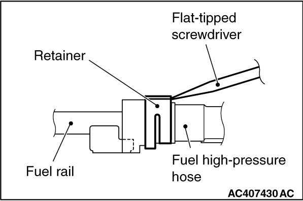
(1)
Insert a flat-tipped screwdriver [6 mm (0.24 inch) wide and 1 mm (0.04inch) thick] into
the retainer of the fuel high-pressure hose connector.
(2)
|
|
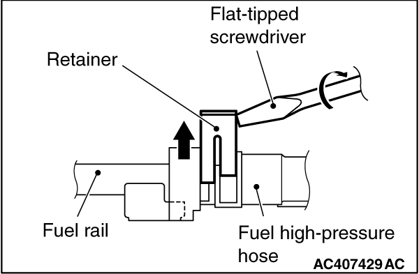
| caution |
When pushing up the retainer of the fuel high-pressure
hose connector, pay attention to avoid damage to the retainer.
|
|
Turn the flat-tipped screwdriver inserted into the retainer by 90 degrees angle to push
up the retainer and unlock the fuel high-pressure hose connector.
2.Disconnect the fuel high-pressure hose.
|
|
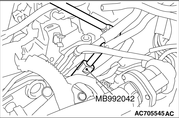
Use special tool MB992042 to remove the engine coolant temperature sensor.
|
|
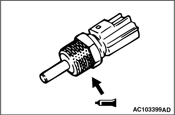
1.Apply the specified sealant to the engine coolant temperature sensor thread.
Specified sealant: Three bond 1324N or equivalent
| note |
Install the engine coolant temperature sensor immediately after applying sealant.
|
|
|
2.
| caution |
After the installation, until a sufficient period of
time (one hour or more) elapses, do not apply the oil or water to the sealant application area
or start the engine.
|
Use special tool MB992042 to tighten the engine coolant temperature sensor to the specified
torque.
Tightening torque: 30 ± 9 N·m (22 ± 7 ft-lb)
|
|
1.Pull up the retainer of fuel high-pressure hose to unlock before installing.
|
|
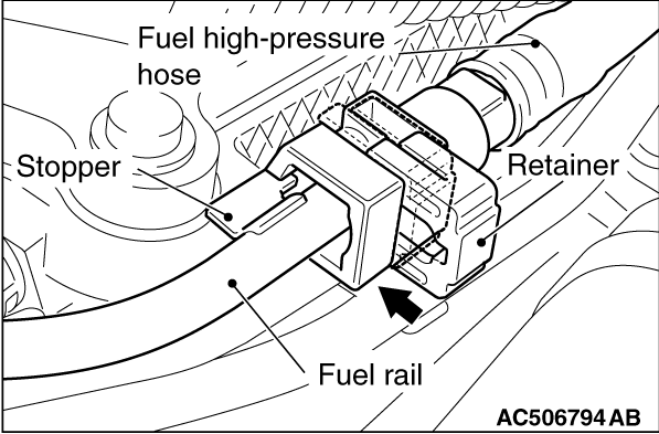
2.Securely insert the fuel rail stopper into the fuel high-pressure hose connector groove
to install the fuel high-pressure hose to the fuel rail.
3.
| caution |
- When pushing in the
retainer of the fuel high-pressure hose connector, pay attention to avoid damage to the retainer.
- After the installation of the fuel high-pressure hose, slightly pull the fuel high-pressure
hose to check that it is connected securely. At this time, also check that there is approximately
1 mm (0.04inch) play.
|
Push in the retainer of the fuel high-pressure hose connector to lock the fuel high-pressure
hose and fuel rail.
|
|
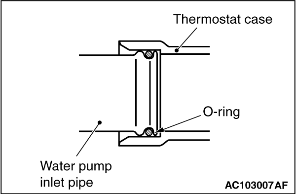
Fit the O-ring in the water pump inlet pipe groove, wet the O-ring circumference or the
pipe mounting area inner wall, and then insert the O-ring.
|
|
1.Insert radiator upper hose as far as the projection of the cooling water outlet hose fitting.
2.Align the mating marks on the radiator upper hose and hose clamp, and then connect
the radiator upper hose.
|
![[Previous]](../../../buttons/fprev.png)
![[Next]](../../../buttons/fnext.png)
)
)
)
)
)
)
)
)
)
)
)
