|
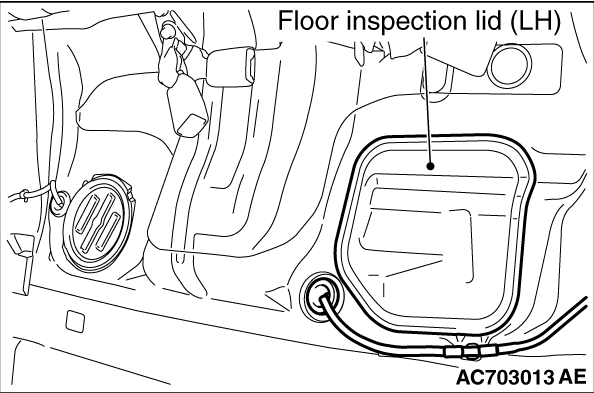
1.Remove the floor inspection lid (LH.)
|
|
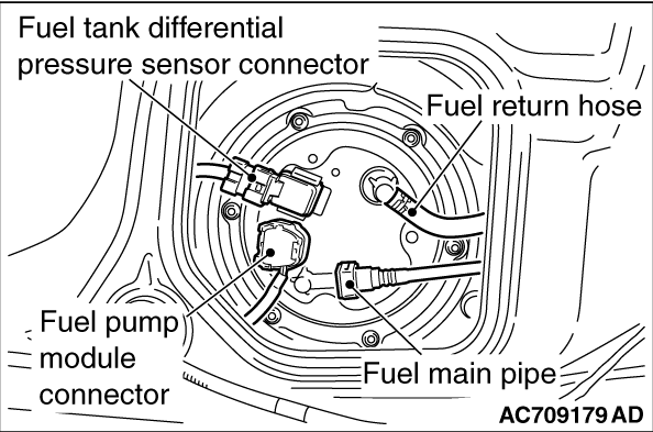
2.Disconnect the fuel pump module connector and fuel tank differential pressure sensor connector.
3.Disconnect the fuel return hose.
|
|
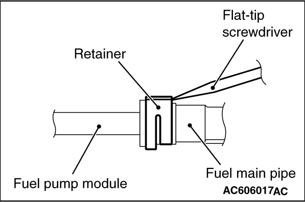
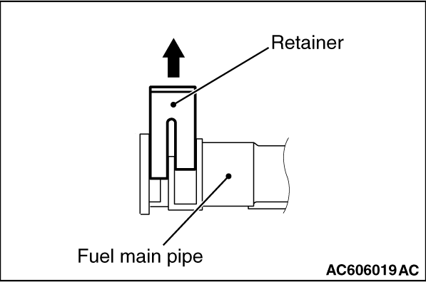
4.Insert a flat-tip screwdriver [6mm (0.24 inch) wide and 1mm (0.04 inch) thick] into
the retainer of the fuel main pipe connector.
|
|
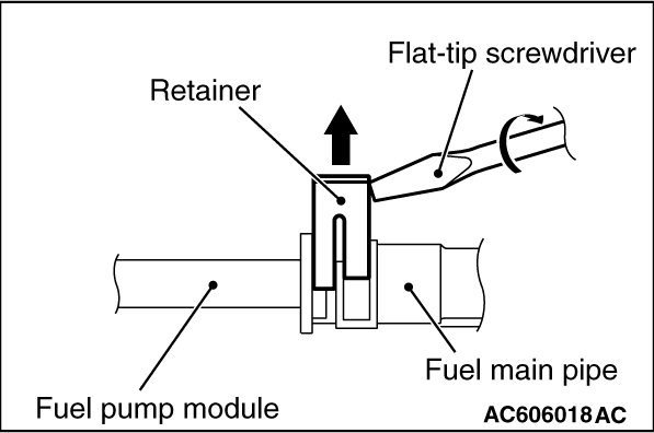
5.
| caution |
When pushing up the retainer of the fuel main pipe connector,
pay attention to avoid damage to the retainer.
|
Turn the flat-tipped screwdriver inserted into the retainer by 90 degrees angle to push
up the retainer and unlock the fuel main pipe.
6.Disconnect the fuel main pipe from the fuel pump module.
|
|
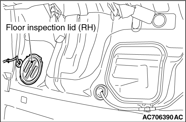
1.Remove the floor inspection lid (RH.)
|
|
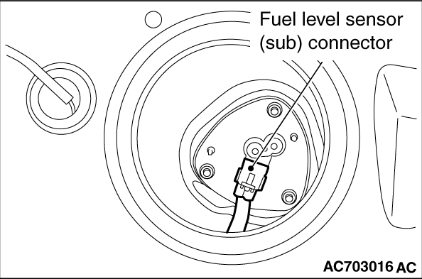
2.Disconnect the fuel level sensor (sub) connector.
|
|
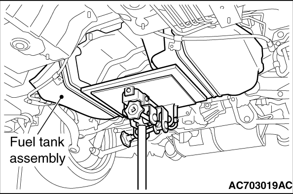
1.Support the fuel tank assembly with a transmission jack to remove the connecting bolts
of fuel tank band and the connecting nuts of fuel tank assembly.
2.Lower the transmission jack slightly and disconnect the fuel filler hose.
3.Tilt the fuel tank assembly, and remove the fuel tank assembly while avoiding the
rear differential carrier.
|
|
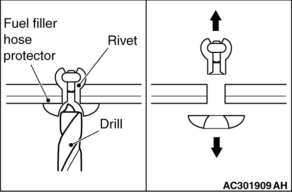
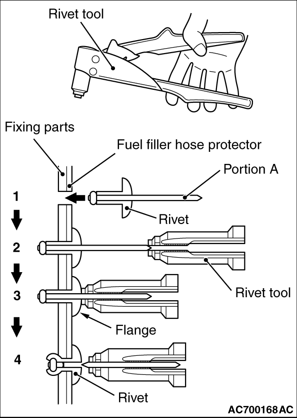
Use a 6.0 / diameter / mm drill to make a hole in the rivet to break
it, and then remove the rivet.
|
|
Use a rivet tool shown in the illustration to connect the parts with rivets by the following
procedures.
1.Insert the rivet into a corresponding location.
2.Set the rivet tool at a portion A of rivet.
3.While pushing the flange surface of the rivet onto parts to be fixed with the rivet
tool, press the handle of the tool.
4.Thin part of portion A of the rivet will be cut off and the parts is fixed in position.
|
|
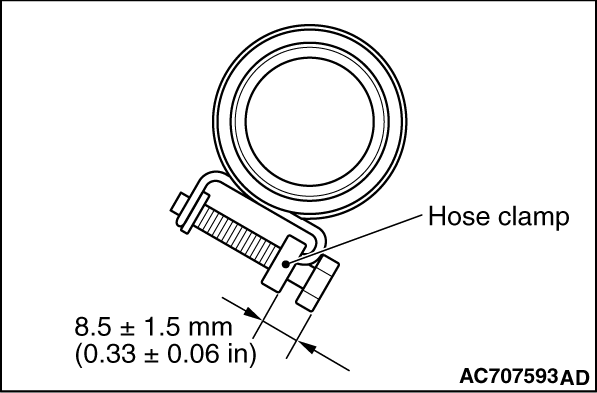
Connect the fuel filler hose, and tighten the bolt of hose clamp so that the bolt tightening
dimension of the hose clump becomes 8.5 ± 1.5 mm (0.33 ± 0.06 inch.)
|
|
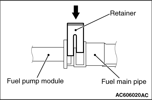
1.Before the installation, push up the retainer of the fuel main pipe connector.
|
|
2.Connect the connector of fuel main pipe to the fuel pump module securely.
3.
| caution |
- When pushing in the
retainer of the fuel high-pressure hose connector, pay attention to avoid damage to the retainer.
- After the installation of the fuel high-pressure hose, slightly pull the fuel high-pressure
hose to check that it is connected securely. At this time, also check that there is approximately
1 mm (0.04inch) play.
|
Push in the retainer of the fuel main pipe connector to lock the fuel main pipe and fuel
pump module.
|
![[Previous]](../../../buttons/fprev.png)
![[Next]](../../../buttons/fnext.png)
)
)
)
)
)
)
)
)
)
)
)
)
)
)
