![[Previous]](../../../buttons/fprev.png)
![[Next]](../../../buttons/fnext.png)
Inspection procedure
23: Ignition switch-ST system and starter relay system <M/T>
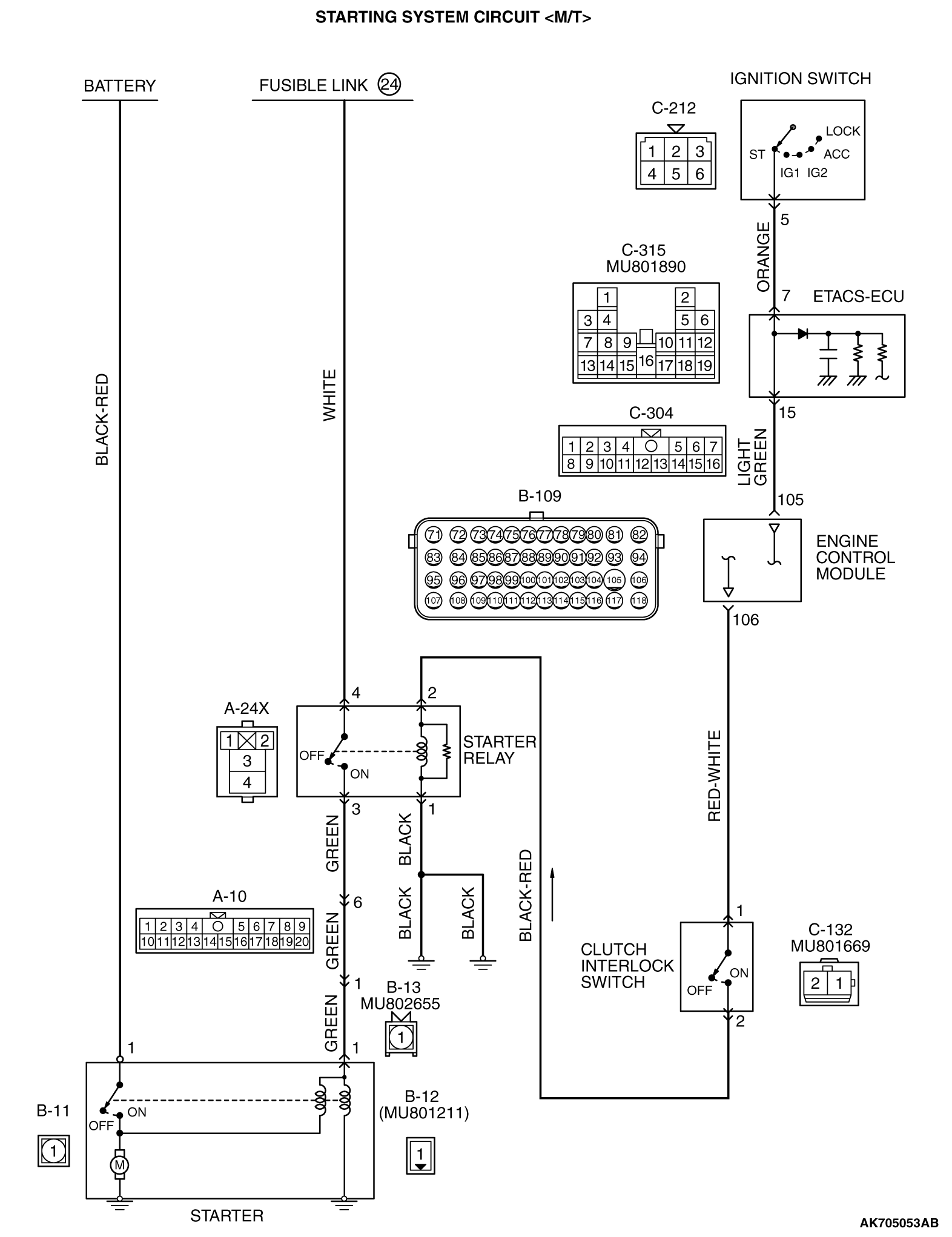
CIRCUIT OPERATION
- If the clutch interlock switch is ON (when the clutch pedal is depressed.)
and the ignition switch is turned to "START" position, battery positive voltage is supplied
to starter relay coil. With this, the starter relay turns "ON" the battery positive voltage
is supplied to the starter motor (terminal No. 1) from the battery.
COMMENT
- Faulty starting system and the related circuit are suspected
to be the causes.
TROUBLESHOOTING HINTS (The most likely causes for this case:)
- Battery failed
- Malfunction of the starter motor relay.
- Malfunction of the starter motor.
- Open circuit or short circuit in the starting system or the related circuit or poor contact
in the connectors
- Malfunction of the clutch interlock switch.
- Malfunction of the ECM
|
|
STEP 1. Using scan tool MB991958, check data list.
|

|
(1)Turn the ignition switch to the "ON" position.
(2)Check the following items of the data list. Refer to Data List Reference Table  . .
- Item 79: Cranking signal.
(3)Turn the ignition switch to the "LOCK" (OFF) position.
Q.
Is the sensor operating properly?
 Go to Step 2. Go to Step 2.
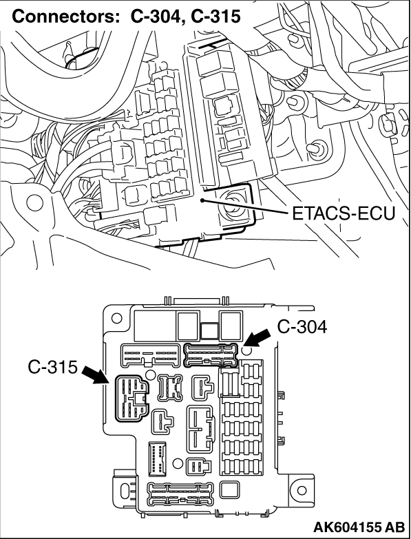
 Repair harness wire between ETACS-ECU connector C-304 (terminal No. 15) and ECM
connector B-109 (terminal No. 105) because of open circuit. Then confirm that the malfunction
symptom is eliminated. Repair harness wire between ETACS-ECU connector C-304 (terminal No. 15) and ECM
connector B-109 (terminal No. 105) because of open circuit. Then confirm that the malfunction
symptom is eliminated.
|
|
|
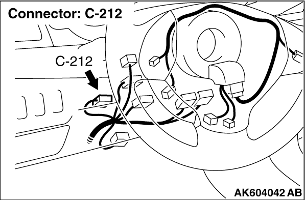
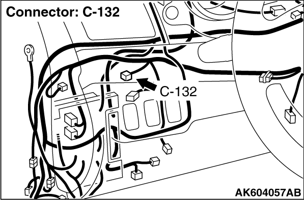
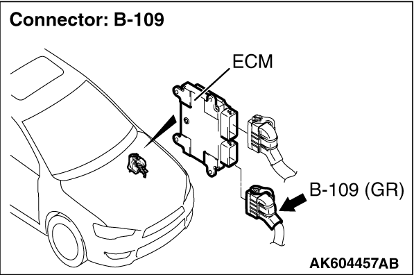
STEP 2. Check harness connector B-132 at clutch interlock switch and
harness connector B-109 at ECM for damage.
|
|
|
Q.
Is the connector in good condition?
|
|
|
Go to Step 3.
|
|
|
|
|
|
Repair or replace it. Refer to GROUP 00E, Harness Connector Inspection .
Then confirm that the malfunction symptom is eliminated.
|
|
|
|
|
|
STEP 3. Check the clutch interlock switch.
|
|
|
Refer to GROUP 21A, Clutch Pedal Check and Master Cylinder - Inspection .
|
|
|
Q.
Are there any abnormalities?
|
|
|
Repair or replace it. Then confirm that the malfunction symptom is eliminated.
|
|
|
|
|
|
Go to Step 4.
|
|
|
|
|
|
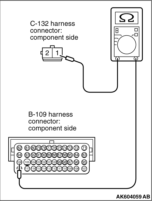
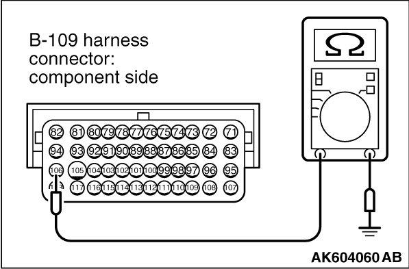
STEP 4. Check for open circuit or short circuit to ground or harness
damage between clutch interlock switch connector B-132 and ECM connector B-109.
|
|
|
(1)Disconnect the connector B-132 and B-109 measure at the harness side.
|
|
(2)Measure the resistance between connector B-132 (terminal No. 1) and connector B-109 (terminal
No. 106).
|
|
(3)Check for the continuity between connector B-109 (terminal No. 106) and ground.
Q.
Is the harness wire in good condition?
Then go to Step 5.
Repair it. Then confirm that the malfunction symptom is eliminated.
|
|
|
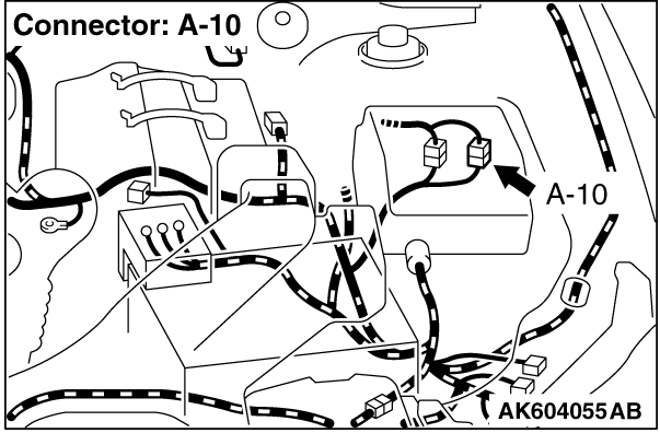
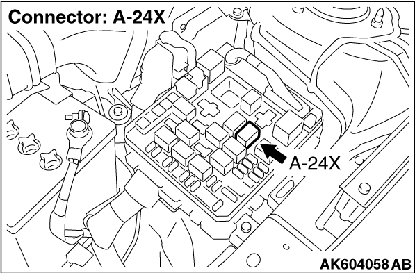
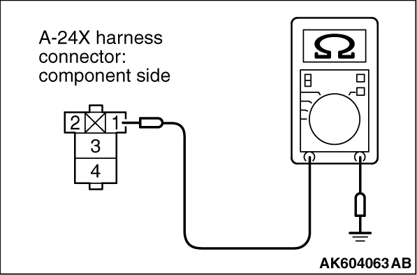
STEP 5. Check harness connector A-24X at starter relay.
|
|
|
Q.
Is the connector in good condition?
|
|
|
Then go to Step 6.
|
|
|
|
|
|
Repair or replace it. Refer to GROUP 00E, Harness Connector Inspection .
Then confirm that the malfunction symptom is eliminated.
|
|
|
|
|
|
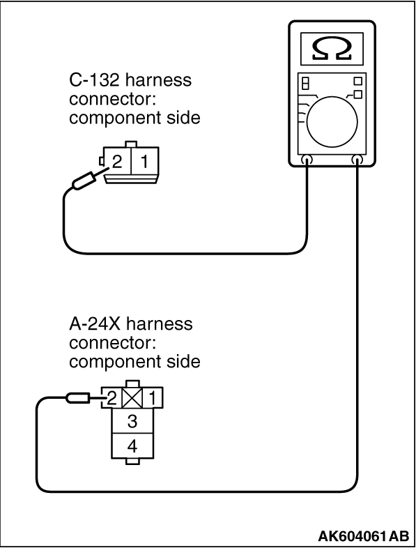
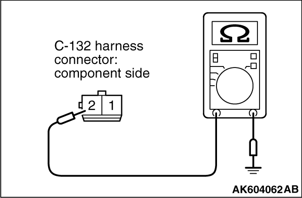
STEP 6. Check for open circuit or short circuit to ground or harness
damage between clutch interlock switch connector C-132 and starter relay connector A-24X.
|
|
(1)Disconnect the connector C-132 and A-24X measure at the harness side.
(2)Measure the resistance between connector C-132 (terminal No. 2) and connector A-24X
(terminal No. 2).
|
|
(3)Check for the continuity between connector C-132 (terminal No. 2) and ground.
Q.
Is the harness wire in good condition?
Then go to Step 7.
Repair it. Then confirm that the malfunction symptom is eliminated.
|
|
|
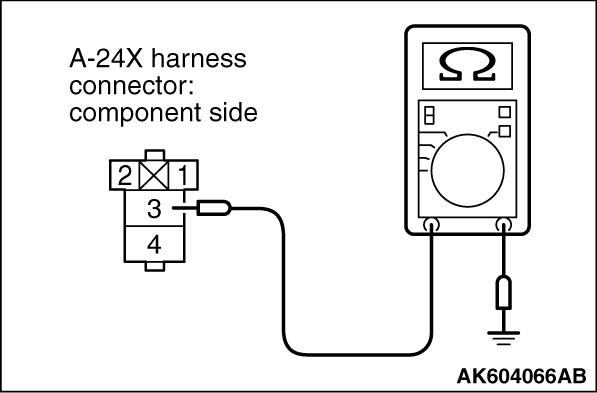
STEP 7. Check for open circuit or harness damage between starter relay
connector A-24X and ground.
|
|
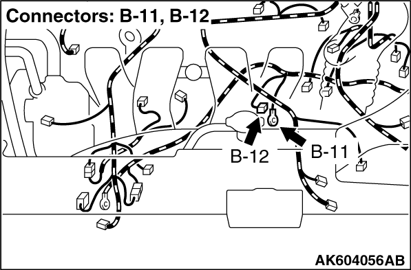
(1)Disconnect the connector A-24X and ground at the harness side.
(2)Measure the resistance between connector A-24X (terminal No. 1) and ground.
Q.
Is the measured resistance less than 2 Ω?
Then go to Step 8.
Repair it. Then confirm that the malfunction symptom is eliminated.
|
|
|
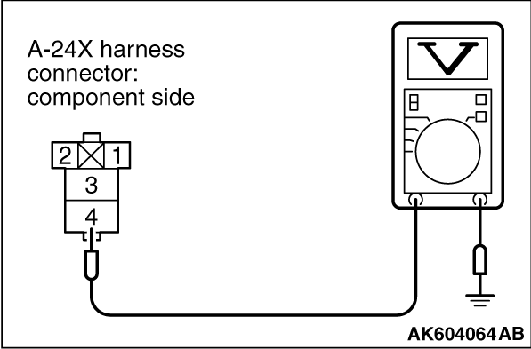
STEP 8. Measure the power supply voltage at starter relay connector
A-24X.
|
|
|
(1)Disconnect the connector A-24X measure at the harness side.
|
|
(2)Measure the voltage between terminal No. 4 and ground.
- Voltage should be battery positive voltage.
Q.
Is battery positive voltage (approximately 12 volts) present?
Go to Step 9.
Repair harness wire between starter relay connector A-24X (terminal No. 4) and
fusible link (24) because of open circuit. Then confirm that the malfunction symptom is eliminated.
|
|
|
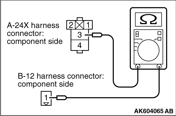
STEP 9. Check for open circuit or short circuit to ground or harness
damage between starter relay connector A-24X and starter motor connector B-12.
|
|
|
(1)Disconnect the connector A-24X and B-12 measure at the harness side.
|
|
(2)Measure the resistance between connector A-24X (terminal No. 3) and connector B-12 (terminal
No. 1).
|
|
(3)Check for the continuity between connector A-24X (terminal No. 3) and ground.
Q.
Is the harness wire in good condition?
Replace the starter motor. Then confirm that the malfunction symptom is eliminated.
Repair it. Then confirm that the malfunction symptom is eliminated.
|
)
)
)
)
)
)
)
)
)
)
)
)
)
)
)
)
)