![[Previous]](../../../buttons/fprev.png)
![[Next]](../../../buttons/fnext.png)
Inspection procedure
22: Fuel pump system
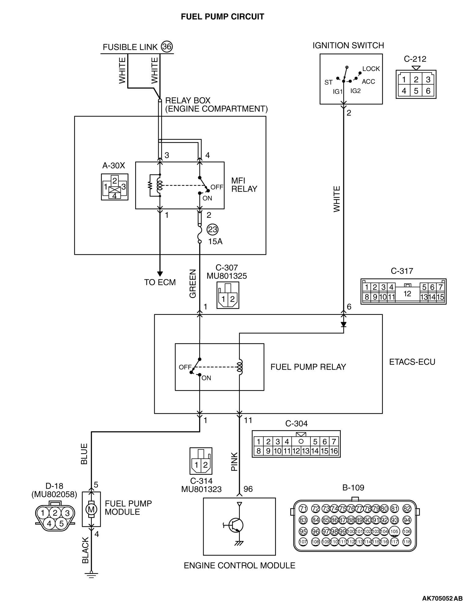
CIRCUIT OPERATION
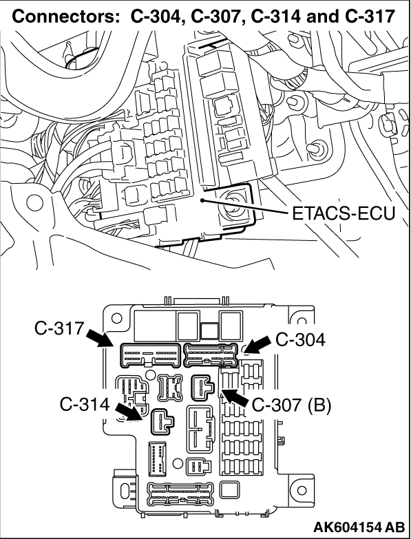
- The fuel pump drive power is supplied from MFI relay (terminal No. 2) to
fuel pump relay (C-307 ETACS-ECU connector terminal No. 1) in the ETACS-ECU.
- The battery positive voltage is applied by the ignition switch to the fuel pump
coil (C-317 ETACS-ECU connector terminal No. 6) in the ETACS-ECU. The ECM turns "ON" the relay by
turning "ON" the power transistor in the unit so as to conduct power to the fuel pump relay
coil (via the C-304 ETACS-ECU connector terminal No. 11).
- When the fuel pump relay is turned "ON", the battery positive voltage will be supplied
from the fuel pump relay (C-314 ETACS-ECU connector terminal No. 1) to the fuel pump.
COMMENT
- When the ignition switch ON signal is inputted into the
ECM, the ECM turns ON the fuel pump relay. This causes the battery voltage to be supplied to
the fuel pump.
TROUBLESHOOTING HINTS (The most likely causes for this code to be set are:)
- Malfunction of the fuel pump relay.
- Malfunction of the fuel pump.
- Improper connector contact, open or short-circulated harness wire.
- Malfunction of the ECM.
|
|
Required Special Tools:
- MB991958: Scan Tool (M.U.T.-III Sub Assembly)
- MB991824: V.C.I.
- MB991827: USB Cable
- MB991910: Main Harness A
|
|
|
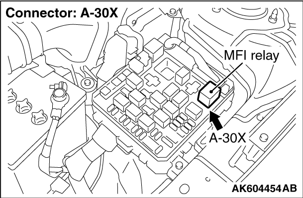
STEP 1. Check harness connector C-304, C-307, C314 and
C-317 at MFI relay for damage.
|
|
|
Q.
Is the connector in good condition?
|
|
|
 Go to Step 2. Go to Step 2.
|
|
|
|
|
|
 Repair or replace it. Refer to GROUP 00E, Harness Connector Inspection Repair or replace it. Refer to GROUP 00E, Harness Connector Inspection  .
Then confirm that the malfunction symptom is eliminated. .
Then confirm that the malfunction symptom is eliminated.
|
|
|
|
|
|
STEP 2. Check the fuel pump relay.
|
|
|
Refer to Fuel Pump Relay Continuity Check .
|
|
|
Q.
Is the measured resistance normal?
|
|
|
Go to Step 3.
|
|
|
|
|
|
Replace the fuel pump relay. Then confirm that the malfunction symptom is eliminated.
|
|
|
|
|
|
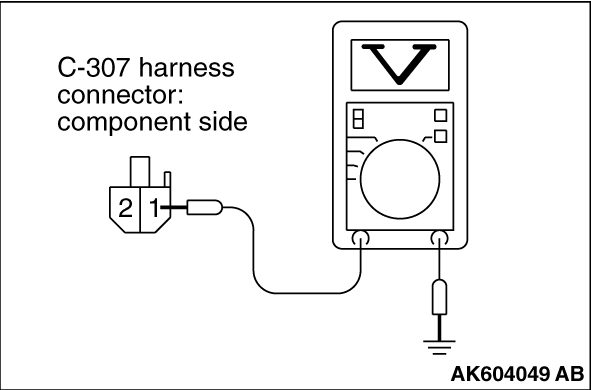
STEP 3. Measure the power supply voltage at ETACS-ECU harness side
connector C-307.
|
|
|
(1)Disconnect the connector C-307 and measure at the harness side.
|
|
(2)Measure the voltage between terminal No. 1 and ground.
- Voltage should measure battery positive voltage.
Q.
Is battery positive voltage (approximately 12 volts) present?
Go to Step 4.
Repair harness wire between relay box (fuse 23) and ETACS-ECU connector C-307
(terminal No. 1) because of open circuit. Then confirm that the malfunction symptom is eliminated.
|
|
|
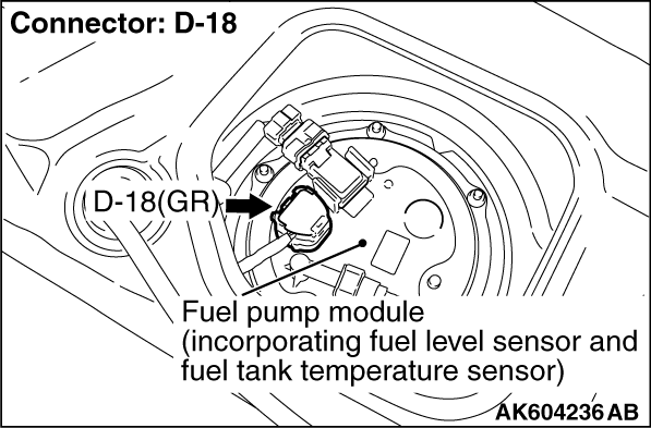
STEP 4. Check connector D-18 at fuel pump for damage.
|
|
|
Q.
Is the connector in good condition?
|
|
|
Go to Step 5.
|
|
|
|
|
|
Repair or replace it. Refer to GROUP 00E, Harness Connector Inspection .
Then confirm that the malfunction symptom is eliminated.
|
|
|
|
|
|
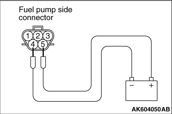
STEP 5. Check the fuel pump operation.
|
|
|
(1)Disconnect fuel pump connector D-18.
|
|
(2)Use jumper wires to connect fuel pump connector terminal No. 5 to the positive battery
terminal and terminal No. 4 to the negative battery terminal.
- An operating sound of the fuel pump should be heard.
Q.
Is the fuel pump operating properly?
Go to Step 6.
Replace the fuel pump. Then confirm that the malfunction symptom is eliminated.
|
|
|
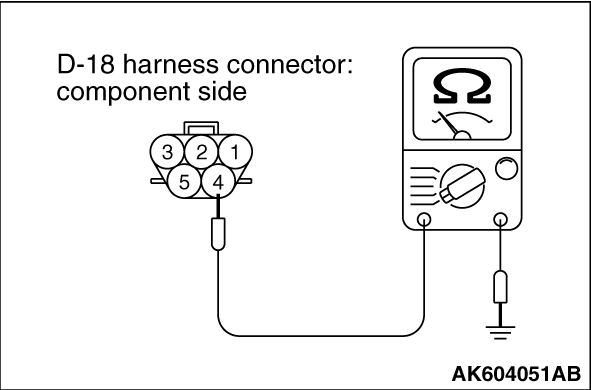
STEP 6. Check for continuity at fuel pump harness side connector D-18.
|
|
|
(1)Disconnect the connector D-18 and measure at the harness side.
|
|
(2)Check for the continuity between terminal No. 4 and ground.
Q.
Does continuity exist?
Go to Step 7.
Repair harness wire between fuel pump connector D-18 (terminal No. 4) and ground
because of open circuit or harness damage. Then confirm that the malfunction symptom is eliminated.
|
|
|
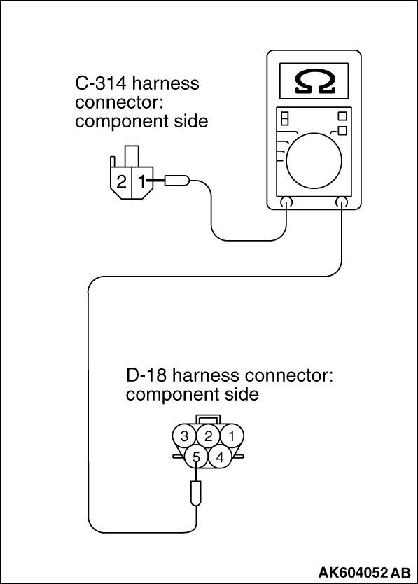
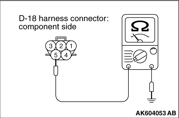
STEP 7. Check for open circuit and short circuit to ground and harness
damage between ETACS-ECU connector C-314 (terminal No. 1) and fuel pump connector D-18 (terminal
No. 5).
|
|
|
(1)Disconnect the connector C-314 and D-18 measure at the harness side.
|
|
(2)Measure the resistance between connector C-314 (terminal No. 1) and connector D-18 (terminal
No. 5).
|
|
(3)Check for the continuity between connector D-18 (terminal No. 5) and ground.
Q.
Is the harness wire in good condition?
Go to Step 8.
Repair it. Then confirm that the malfunction symptom is eliminated.
|
|
|
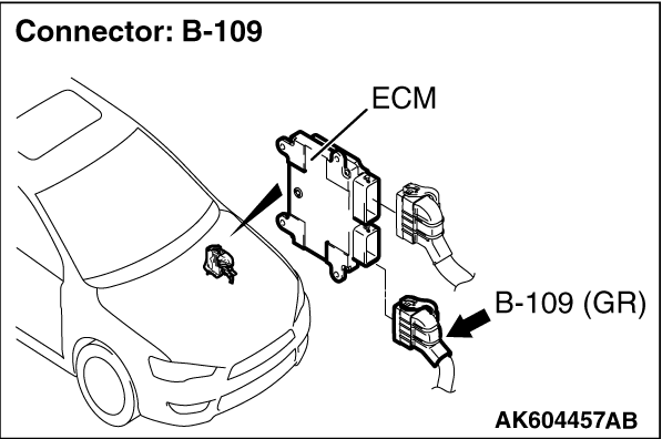
STEP 8. Check connector B-109 at ECM for damage.
|
|
|
Q.
Is the connector in good condition?
|
|
|
Go to Step 9.
|
|
|
|
|
|
Repair or replace it. Refer to GROUP 00E, Harness Connector Inspection .
Then confirm that the malfunction symptom is eliminated.
|
|
|
|
|
|
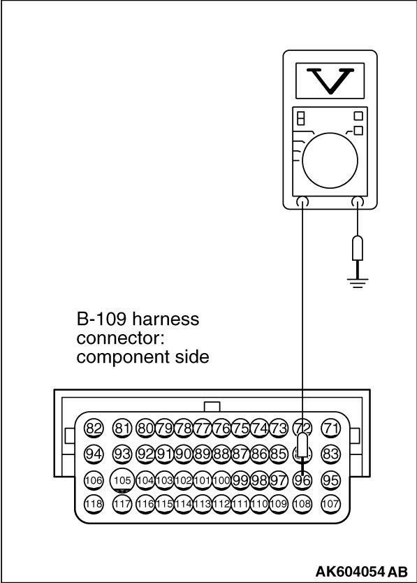
STEP 9. Measure the power supply voltage at ECM connector B-109.
|
|
|
(1)Disconnect the connector B-109 and measure at the harness side.
|
|
|
(2)Turn the ignition switch to the "ON" position.
|
|
(3)Measure the voltage between terminal No. 96 and ground.
- Voltage should be battery positive voltage.
(4)Turn the ignition switch to the "LOCK" (OFF) position.
Q.
Is battery positive voltage (approximately 12 volts) present?
Replace the ECM. When the ECM is replaced, register the ID code. Refer to GROUP
42B, Diagnosis - ID Code Registration Judgment Table <Vehicles with KOS> or
GROUP 42C, Diagnosis - ID Codes Registration Judgment Table <Vehicles with WCM> .
Repair harness wire between ETACS-ECU connector C-304 (terminal No. 11) and ECM
connector B-109 (terminal No. 96) because of open circuit. Then confirm that the malfunction
symptom is eliminated.
|
)
)
)
)
)
)
)
)
)
)
)
)