![[Previous]](../../../buttons/fprev.png)
![[Next]](../../../buttons/fnext.png)
Inspection procedure
23: Fuel pump system
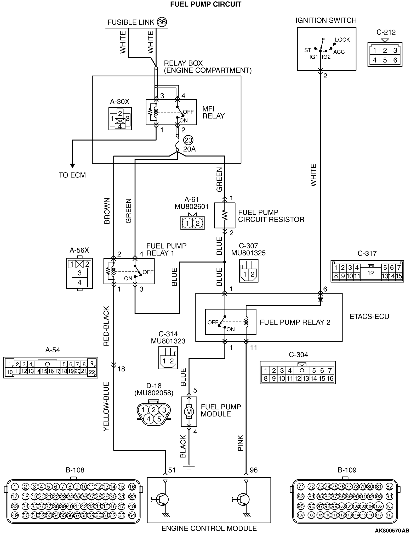
CIRCUIT OPERATION
- The power supply is supplied from the MFI relay (terminal No. 2) to the fuel
pump relay 1 (terminal No. 4) and the fuel pump circuit resistor (terminal No. 1).
- The battery positive voltage is applied to the fuel pump relay 1 (terminal No. 2)
from the MFI relay (terminal No. 2).
- The battery positive voltage is applied from the ignition switch to the fuel pump
relay 2 (C-317 ETACS-ECU connector terminal No. 6).
- The ECM (terminal No. 96) turns ON the power transistor of the unit during the engine
cranking and running. The current is going through the fuel pump relay 2 (C-304 ETACS-ECU connector terminal
No. 11), and then the relay is turned ON.
- When the fuel pump relay 2 is turned ON, the fuel pump drive power is supplied from
the fuel pump relay 2 (C-314 ETACS-ECU connector terminal No. 1) to the fuel pump (terminal
No. 5).
- When the vehicle is driven at low engine loads, the ECM (terminal No. 51) turns
OFF the power transistor of the unit. The current is not going through the fuel pump relay 1,
and then the relay is turned OFF.
- When the vehicle is driven at high engine loads, the ECM (terminal No. 51) turns
ON the power transistor of the unit. The current is going through the fuel pump relay 1 (terminal
No. 1), and then the relay is turned ON. Thus the fuel pump drive power is supplied from the
fuel pump relay 1 (terminal No. 3) to the fuel pump relay 2 (C-307 ETACS-ECU connector terminal
No. 1).
COMMENT
- The ECM turns ON the fuel pump relay 2 during the engine
cranking and running, and then supplies the drive power to the fuel pump.
- The ECM supplies the drive power to the fuel pump via the resistor during the engine
running at low engine loads. The ECM supplies the drive power directly to the fuel pump during
the engine running at high engine loads to increase the fuel discharge rate of fuel pump.
TROUBLESHOOTING HINTS (The most likely causes for this case:)
- Fuel pump relay 1 failed.
- Fuel pump relay 2 of ETACS-ECU failed.
- Fuel pump failed.
- Fuel pump circuit resistor failed.
- Improper connector contact, open or short-circulated harness wire.
- ECM failed.
|
|
Required Special Tools:
- MB991958: Scan Tool (M.U.T.-III Sub Assembly)
- MB991824: V.C.I.
- MB991827: USB Cable
- MB991910: Main Harness A
|
|
|
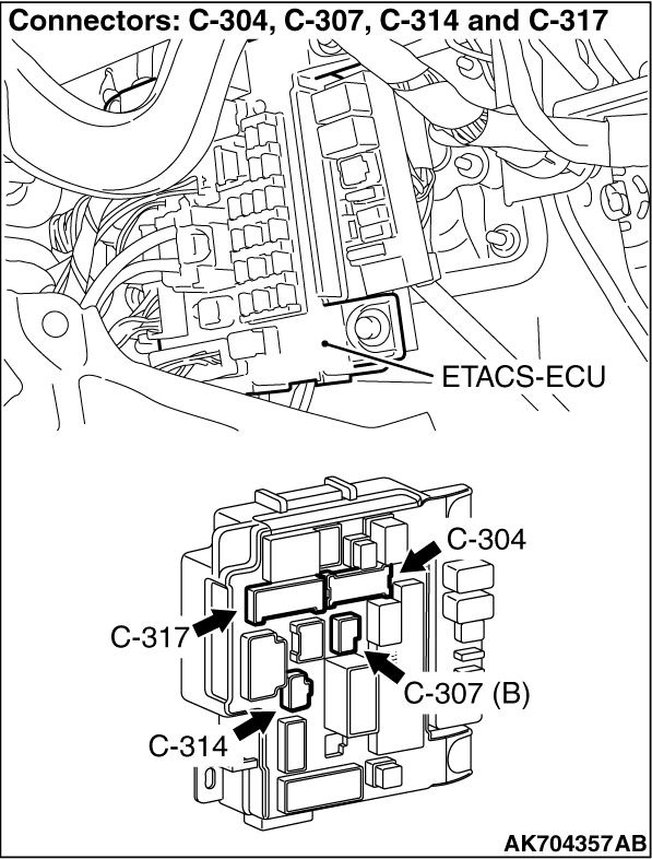
STEP 1. Check harness connector C-304, C-307, C314 and C-317
at ETACS-ECU for damage.
|
|
|
Q.
Are the harness connectors in good condition?
|
|
|
 Go to Step 2. Go to Step 2.
|
|
|
|
|
|
 Repair or replace them. Refer to GROUP 00E, Harness Connector Inspection Repair or replace them. Refer to GROUP 00E, Harness Connector Inspection  .
Then confirm that the malfunction symptom is eliminated. .
Then confirm that the malfunction symptom is eliminated.
|
|
|
|
|
|
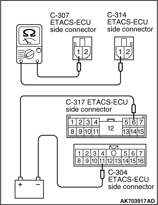
STEP 2. Check the fuel pump relay 2.
|
|
(2)Use jumper wires to connect C-317 ETACS-ECU terminal No. 6 to the positive battery terminal
and C-304 ETACS-ECU terminal No. 11 to the negative battery terminal.
(3)Check for continuity between the C-307 ETACS-ECU terminal No. 1 and C-314 ETACS-ECU
terminal No. 1 while connecting and disconnecting the jumper wire at the negative battery terminal.
- Continuity (2 ohms or less) <Negative battery terminal connected>
- Should be open loop. <Negative battery terminal disconnected>
(4)Install the ETACS-ECU.
Q.
Is the measured resistance normal?
Go to Step 3.
Replace the ETACS-ECU. Then confirm that the malfunction symptom is eliminated.
|
|
|
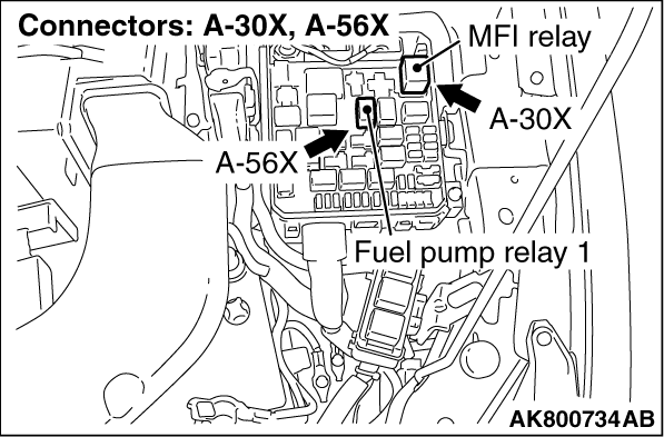
STEP 3. Check harness connector A-56X at fuel pump relay 1 for damage.
|
|
|
Q.
Is the harness connector in good condition?
|
|
|
Go to Step 4.
|
|
|
|
|
|
Repair or replace it. Refer to GROUP 00E, Harness Connector Inspection .
Then confirm that the malfunction symptom is eliminated.
|
|
|
|
|
|
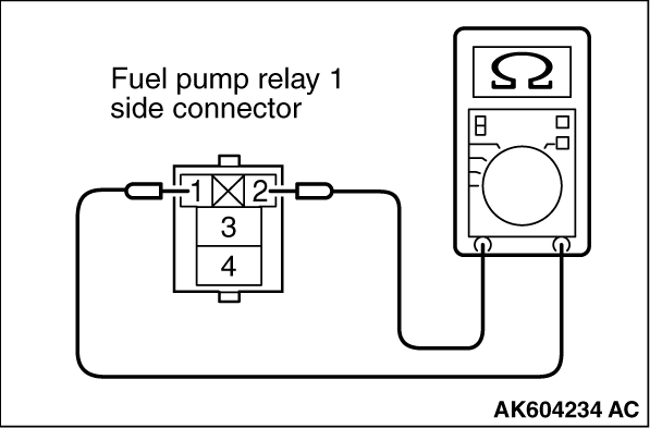
STEP 4. Check the fuel pump relay 1.
|
|
|
(1)Remove the fuel pump relay 1.
|
|
(2)Check for continuity between the fuel pump relay 1 terminal No. 1 and No. 2.
- There should be continuity.
|
|
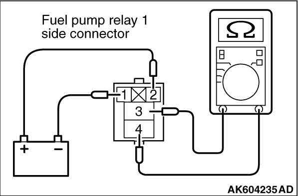
(3)Use jumper wires to connect fuel pump relay 1 terminal No. 2 to the positive battery terminal
and terminal No. 1 to the negative battery terminal.
(4)Check for continuity between the fuel pump relay 1 terminal No. 3 and No. 4 while
connecting and disconnecting the jumper wire at the negative battery terminal.
- Continuity (2 ohms or less) <Negative battery terminal connected.>
- Should be open loop. <Negative battery terminal disconnected.>
(5)Install the fuel pump relay 1.
Q.
Is the measured resistance normal?
Go to Step 5.
Replace the fuel pump relay 1. Then confirm that the malfunction symptom is eliminated.
|
|
|
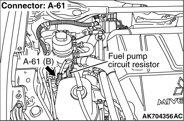
STEP 5. Check harness connector A-61 fuel pump circuit resistor.
|
|
|
Q.
Is the harness connector in good condition?
|
|
|
Go to Step 6.
|
|
|
|
|
|
Repair or replace it. Refer to GROUP 00E, Harness Connector Inspection .
Then confirm that the malfunction symptom is eliminated.
|
|
|
|
|
|
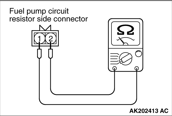
STEP 6. Check the fuel pump circuit resistor.
|
|
|
(1)Disconnect the fuel pump circuit resistor connector A-61.
|
|
(2)Measure the resistance between fuel pump circuit resistor side connector terminal No.
1 and No. 2.
Standard value: 0.45 - 0.65 Ω [at 20°C (68°F)]
Q.
Is the measured resistance between 0.45 and 0.65 Ω [at 20°C
(68°F)]?
Go to Step 7.
Replace the fuel pump circuit resistor. Then confirm that the malfunction symptom
is eliminated.
|
|
|
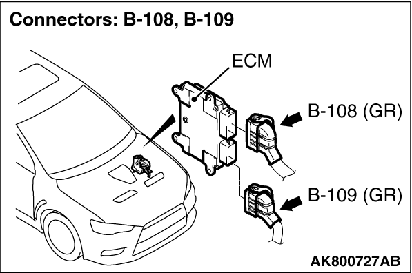
STEP 7. Check harness connector B-109 at ECM for damage.
|
|
|
Q.
Is the harness connector in good condition?
|
|
|
Go to Step 8.
|
|
|
|
|
|
Repair or replace it. Refer to GROUP 00E, Harness Connector Inspection .
Then confirm that the malfunction symptom is eliminated.
|
|
|
|
|
|
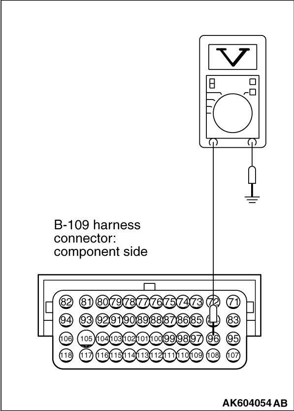
STEP 8. Measure the power supply voltage at ECM harness side connector
B-109.
|
|
|
(1)Disconnect the connector B-109 and measure at the harness side.
|
|
|
(2)Turn the ignition switch to the "ON" position.
|
|
(3)Measure the voltage between terminal No. 96 and ground.
- Voltage should be battery positive voltage.
(4)Turn the ignition switch to the "LOCK" (OFF) position.
Q.
Is battery positive voltage (approximately 12 volts) present?
Go to Step 9.
Repair harness wire between ETACS-ECU connector C-304 (terminal No. 11) and ECM
connector B-109 (terminal No. 96) because of open circuit. Then confirm that the malfunction
symptom is eliminated.
|
|
|
STEP 9. Check harness connector B-108 at ECM for damage.
|
|
|
Q.
Is the harness connector in good condition?
|
|
|
Go to Step 10.
|
|
|
|
|
|
Repair or replace it. Refer to GROUP 00E, Harness Connector Inspection .
Then confirm that the malfunction symptom is eliminated.
|
|
|
|
|
|
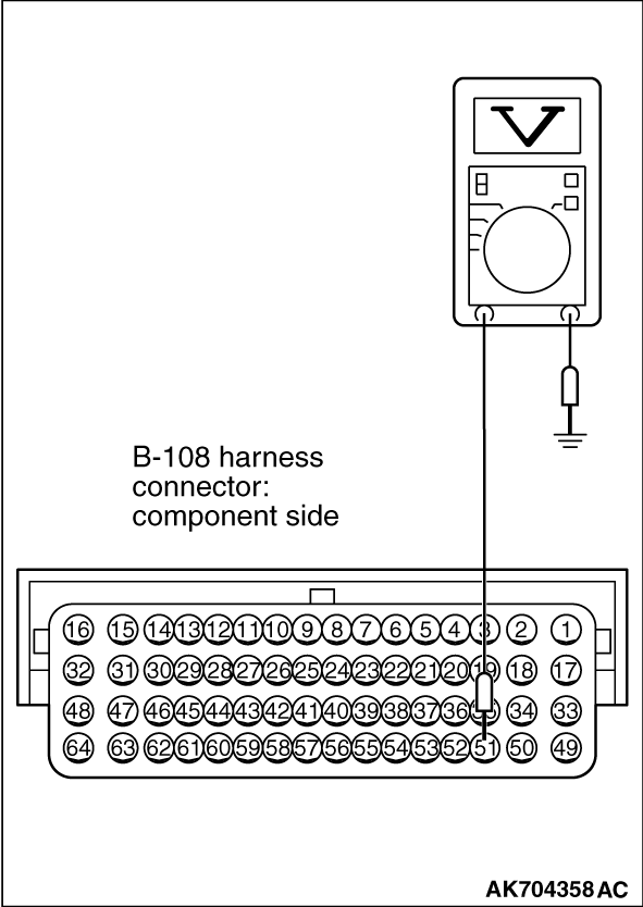
STEP 10. Measure the power supply voltage at ECM harness side connector
B-108.
|
|
|
(1)Disconnect the connector B-108 and measure at the harness side.
|
|
|
(2)Turn the ignition switch to the "ON" position.
|
|
(3)Measure the voltage between terminal No. 51 and ground.
- Voltage should be battery positive voltage.
(4)Turn the ignition switch to the "LOCK" (OFF) position.
Q.
Is battery positive voltage (approximately 12 volts) present?
Go to Step 13.
Go to Step 11.
|
|
|
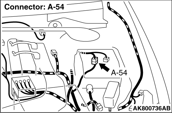
STEP 11. Check for open circuit and short circuit to ground between
fuel pump relay 1 connector A-56X (terminal No. 1) and ECM connector B-108 (terminal No. 51).
|
|
|
| note |
Check harness after checking intermediate connector A-54. If intermediate connector is
damaged, repair or replace it. Refer to GROUP 00E, Harness Connector Inspection . Then
confirm that the malfunction symptom is eliminated.
|
|
|
|
Q.
Is the harness wire in good condition?
|
|
|
Go to Step 12.
|
|
|
|
|
|
Repair it. Then confirm that the malfunction symptom is eliminated.
|
|
|
|
|
|
STEP 12. Check harness connector A-30X at MFI relay for damage.
|
|
|
Q.
Is the harness connector in good condition?
|
|
|
Repair harness wire between fuel pump relay 1 connector A-56X (terminal No. 2)
and MFI relay connector A-30X (terminal No. 2) because of open circuit. Then confirm that the
malfunction symptom is eliminated.
|
|
|
|
|
|
Repair or replace it. Refer to GROUP 00E, Harness Connector Inspection .
Then confirm that the malfunction symptom is eliminated.
|
|
|
|
|
|
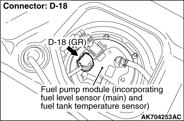
STEP 13. Check harness connector D-18 at fuel pump for damage.
|
|
|
Q.
Is the harness connector in good condition?
|
|
|
Go to Step 14.
|
|
|
|
|
|
Repair or replace it. Refer to GROUP 00E, Harness Connector Inspection .
Then confirm that the malfunction symptom is eliminated.
|
|
|
|
|
|
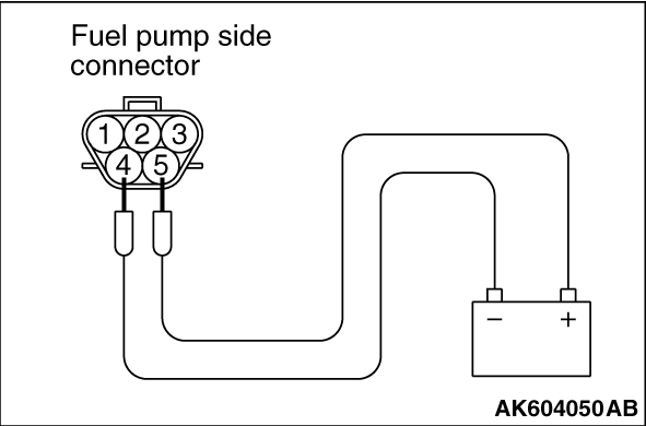
STEP 14. Check the fuel pump operation.
|
|
|
(1) Disconnect fuel pump connector D-18.
|
|
(2) Use jumper wires to connect fuel pump terminal No. 5 to the positive battery terminal
and terminal No. 4 to the negative battery terminal.
- An operating sound of the fuel pump should be heard.
Q.
Is the fuel pump operating properly?
Go to Step 15.
Replace the fuel pump. Then confirm that the malfunction symptom is eliminated.
|
|
|
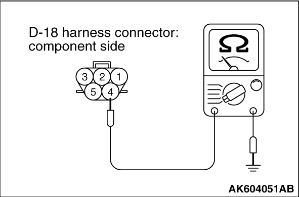
STEP 15. Check the continuity at fuel pump harness side connector
D-18.
|
|
|
(1)Disconnect the connector D-18 and measure at the harness side.
|
|
(2) Check for the continuity between terminal No. 4 and ground.
- Continuity (2 ohms or less).
Q.
Does continuity exist?
Go to Step 16.
Repair harness wire between fuel pump connector D-18 (terminal No. 4) and ground
because of open circuit or harness damage. Then confirm that the malfunction symptom is eliminated.
|
|
|
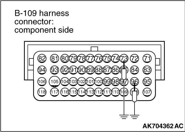
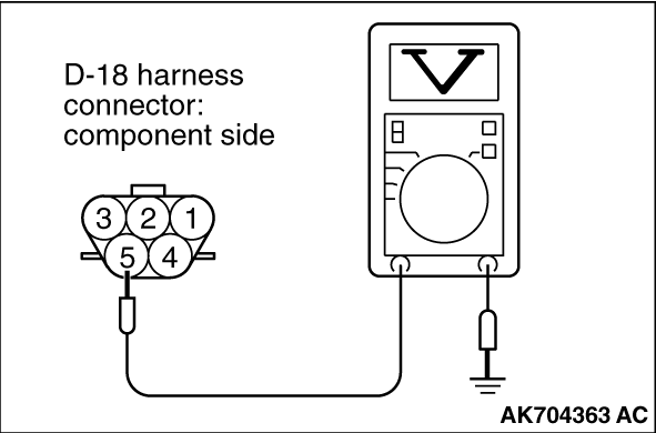
STEP 16. Measure the power supply voltage at fuel pump harness side
connector D-18.
|
|
|
(1)Disconnect the connector D-18 and measure at the harness side.
|
|
(2)Disconnect the ECM connector B-109, and connect terminal No. 73 and No. 96 to ground using
a jumper wire.
(3)Turn the ignition switch to the "ON" position.
|
|
(4)Measure the voltage between terminal No. 5 and ground.
- Voltage should be battery positive voltage.
(5)Turn the ignition switch to the "LOCK" (OFF) position.
Q.
Is battery positive voltage (approximately 12 volts) present?
Go to Step 22.
Go to Step 17.
|
|
|
STEP 17. Check for open circuit and short circuit to ground between
fuel pump connector D-18 (terminal No. 5) and ETACS-ECU connector C-314 (terminal No. 1).
|
|
|
Q.
Is the harness wire in good condition?
|
|
|
Go to Step 18.
|
|
|
|
|
|
Repair it. Then confirm that the malfunction symptom is eliminated.
|
|
|
|
|
|
STEP 18. Check for open circuit and short circuit to ground between
fuel pump circuit resistor connector A-61 (terminal No. 2) and ETACS-ECU connector C-307 (terminal No.
1).
|
|
|
Q.
Is the harness wire in good condition?
|
|
|
Go to Step 19.
|
|
|
|
|
|
Repair it. Then confirm that the malfunction symptom is eliminated.
|
|
|
|
|
|
STEP 19. Check harness connector A-30X at MFI relay for damage.
|
|
|
Q.
Is the harness connector in good condition?
|
|
|
Go to Step 20.
|
|
|
|
|
|
Repair or replace it. Refer to GROUP 00E, Harness Connector Inspection .
Then confirm that the malfunction symptom is eliminated.
|
|
|
|
|
|
STEP 20. Check for open circuit and short circuit to ground between
MFI relay connector A-30X (terminal No. 2) and fuel pump circuit resistor connector A-61 (terminal No.
1).
|
|
|
Q.
Is the harness wire in good condition?
|
|
|
Go to Step 21.
|
|
|
|
|
|
Repair it. Then confirm that the malfunction symptom is eliminated.
|
|
|
|
|
|
STEP 21. Check for short circuit to ground between fuel pump relay
1 connector A-56X (terminal No. 3) and ETACS-ECU connector C-307 (terminal No. 1).
|
|
|
Q.
Is the harness wire in good condition?
|
|
|
Repair harness wire between ETACS-ECU connector C-304 (terminal No. 11) and ECM
connector B-109 (terminal No. 96) because of harness damage. Then confirm that the malfunction
symptom is eliminated.
|
|
|
|
|
|
Repair it. Then confirm that the malfunction symptom is eliminated.
|
|
|
|
|
|
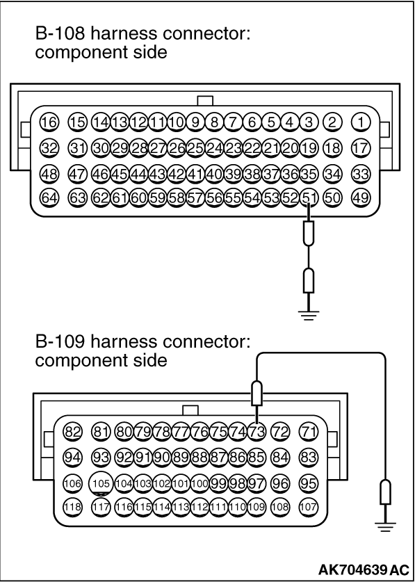
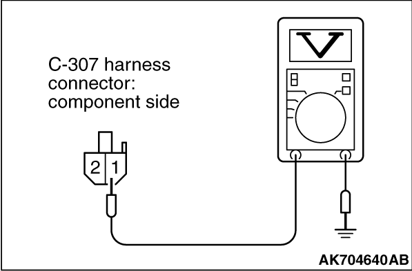
STEP 22. Measure the power supply voltage at ETACS-ECU harness side
connector C-307.
|
|
|
(1)Disconnect the connector C-307 and measure at the harness side.
|
|
|
(2)Disconnect the fuel pump circuit resistor connector A-61.
|
|
(3)Disconnect the ECM connector B-108, and connect terminal No. 51 to ground using a jumper
wire.
(4)Disconnect the ECM connector B-109, and connect terminal No. 73 to ground using
a jumper wire.
(5)Turn the ignition switch to the "ON" position.
|
|
(6)Measure the voltage between terminal No. 1 and ground.
- Voltage should be battery positive voltage.
(7)Turn the ignition switch to the "LOCK" (OFF) position.
Q.
Is battery positive voltage (approximately 12 volts) present?
Go to Step 27.
Go to Step 23.
|
|
|
STEP 23. Check for open circuit between fuel pump relay 1 connector
A-56X (terminal No. 3) and ETACS-ECU connector C-307 (terminal No. 1).
|
|
|
Q.
Is the harness wire in good condition?
|
|
|
Go to Step 24.
|
|
|
|
|
|
Repair it. Then confirm that the malfunction symptom is eliminated.
|
|
|
|
|
|
STEP 24. Check harness connector A-30X at MFI relay for damage.
|
|
|
Q.
Is the harness connector in good condition?
|
|
|
Go to Step 25.
|
|
|
|
|
|
Repair or replace it. Refer to GROUP 00E, Harness Connector Inspection .
Then confirm that the malfunction symptom is eliminated.
|
|
|
|
|
|
STEP 25. Check for open circuit and short circuit to ground between
fuel pump relay 1 connector A-56X (terminal No. 4) and MFI relay connector A-30X (terminal No.
2).
|
|
|
Q.
Is the harness wire in good condition?
|
|
|
Go to Step 26.
|
|
|
|
|
|
Repair it. Then confirm that the malfunction symptom is eliminated.
|
|
|
|
|
|
STEP 26. Check for harness damage between fuel pump relay 1 connector
A-56X (terminal No. 1) and ECM connector B-108 (terminal No. 51).
|
|
|
| note |
Check harness after checking intermediate connector A-54. If intermediate connector is
damaged, repair or replace it. Refer to GROUP 00E, Harness Connector Inspection . Then
confirm that the malfunction symptom is eliminated.
|
|
|
|
Q.
Is the harness wire in good condition?
|
|
|
Repair harness wire between fuel pump relay 1 connector A-56X (terminal No. 2)
and MFI relay connector A-30X (terminal No. 2) because of harness damage. Then confirm that
the malfunction symptom is eliminated.
|
|
|
|
|
|
Repair it. Then confirm that the malfunction symptom is eliminated.
|
|
|
|
|
|
STEP 27. Check for harness damage between fuel pump connector D-18
(terminal No. 5) and ETACS-ECU connector C-314 (terminal No. 1).
|
|
|
Q.
Is the harness wire in good condition?
|
|
|
Go to Step 28.
|
|
|
|
|
|
Repair it. Then confirm that the malfunction symptom is eliminated.
|
|
|
|
|
|
STEP 28. Check for harness damage between fuel pump circuit resistor
connector A-61 (terminal No. 2) and ETACS-ECU connector C-307 (terminal No. 1).
|
|
|
Q.
Is the harness wire in good condition?
|
|
|
Go to Step 29.
|
|
|
|
|
|
Repair it. Then confirm that the malfunction symptom is eliminated.
|
|
|
|
|
|
STEP 29. Check harness connector A-30X at MFI relay for damage.
|
|
|
Q.
Is the harness connector in good condition?
|
|
|
Go to Step 30.
|
|
|
|
|
|
Repair or replace it. Refer to GROUP 00E, Harness Connector Inspection .
Then confirm that the malfunction symptom is eliminated.
|
|
|
|
|
|
STEP 30. Check for harness damage between MFI relay connector A-30X
(terminal No. 2) and fuel pump circuit resistor connector A-61 (terminal No. 1).
|
|
|
Q.
Is the harness wire in good condition?
|
|
|
Go to Step 31.
|
|
|
|
|
|
Repair it. Then confirm that the malfunction symptom is eliminated.
|
|
|
|
|
|
STEP 31. Check for harness damage between fuel pump relay 1 connector
A-56X (terminal No. 3) and ETACS-ECU connector C-307 (terminal No. 1).
|
|
|
Q.
Is the harness wire in good condition?
|
|
|
Go to Step 32.
|
|
|
|
|
|
Repair it. Then confirm that the malfunction symptom is eliminated.
|
|
|
|
|
|
STEP 32. Check for harness damage between fuel pump relay 1 connector
A-56X (terminal No. 4) and MFI relay connector A-30X (terminal No. 2).
|
|
|
Q.
Is the harness wire in good condition?
|
|
|
Go to Step 33.
|
|
|
|
|
|
Repair it. Then confirm that the malfunction symptom is eliminated.
|
|
|
|
|
|
STEP 33. Using scan tool MB991958, check actuator test item 9: Fuel
Pump.
|

|
| caution |
To prevent damage to scan tool MB991958, always turn the ignition
switch to the "LOCK" (OFF) position before connecting or disconnecting scan tool MB991958.
|
(1)Connect scan tool MB991958 to the data link connector.
(2)Turn the ignition switch to the "ON" position.
(3)Set scan tool MB991958 to the actuator test mode for item 9, Fuel Pump.
(4)Turn the ignition switch to the "LOCK" (OFF) position.
Q.
Is the fuel pump operating properly?
It can be assumed that this malfunction is intermittent, Refer to GROUP 00, How
to Use Troubleshooting - Inspection Service Points - How to Cope with Intermittent
Malfunctions .
Replace the ECM. When the ECM is replaced, register the ID code. Refer to GROUP
42B, Diagnosis - ID Code Registration Necessity Judgment Table <Vehicles with KOS> or
GROUP 42C, Diagnosis - ID Codes Registration Judgment Table <Vehicles with WCM> .
Then confirm that the malfunction symptom is eliminated.
|
)
)
)
)
)
)
)
)
)
)
)
)
)
)
)
)
)
)
)
)
)