![[Previous]](../../../buttons/fprev.png)
![[Next]](../../../buttons/fnext.png)
DTC P0455: Evaporative
Emission System Leak Detected (Gross Leak)
TECHNICAL DESCRIPTION
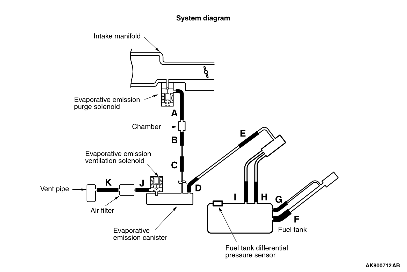
- The fuel tank may be under a slight pressure or vacuum depending on the state
of the Evaporative Emission (EVAP) System. The ECM monitors and responds to these pressure/vacuum
changes. If the pressure/vacuum varies from the specified range, the ECM will set DTC P0455.
- The ECM energizes the evaporative emission ventilation solenoid to shut off the
evaporative emission canister outlet port.
- The evaporative emission purge solenoid is activated to apply engine manifold vacuum
to the EVAP system.
- When the fuel system develops a vacuum of 2 kPa (0.29 psi), the evaporative emission
purge solenoid is turned "off" and the fuel system vacuum is maintained at 2 kPa (0.29 psi).
- The ECM determines whether there is a leak or clog in the fuel system by measuring
the change in vacuum inside the fuel tank.
- The test is stopped when fuel vapor pressure is determined to be too high.
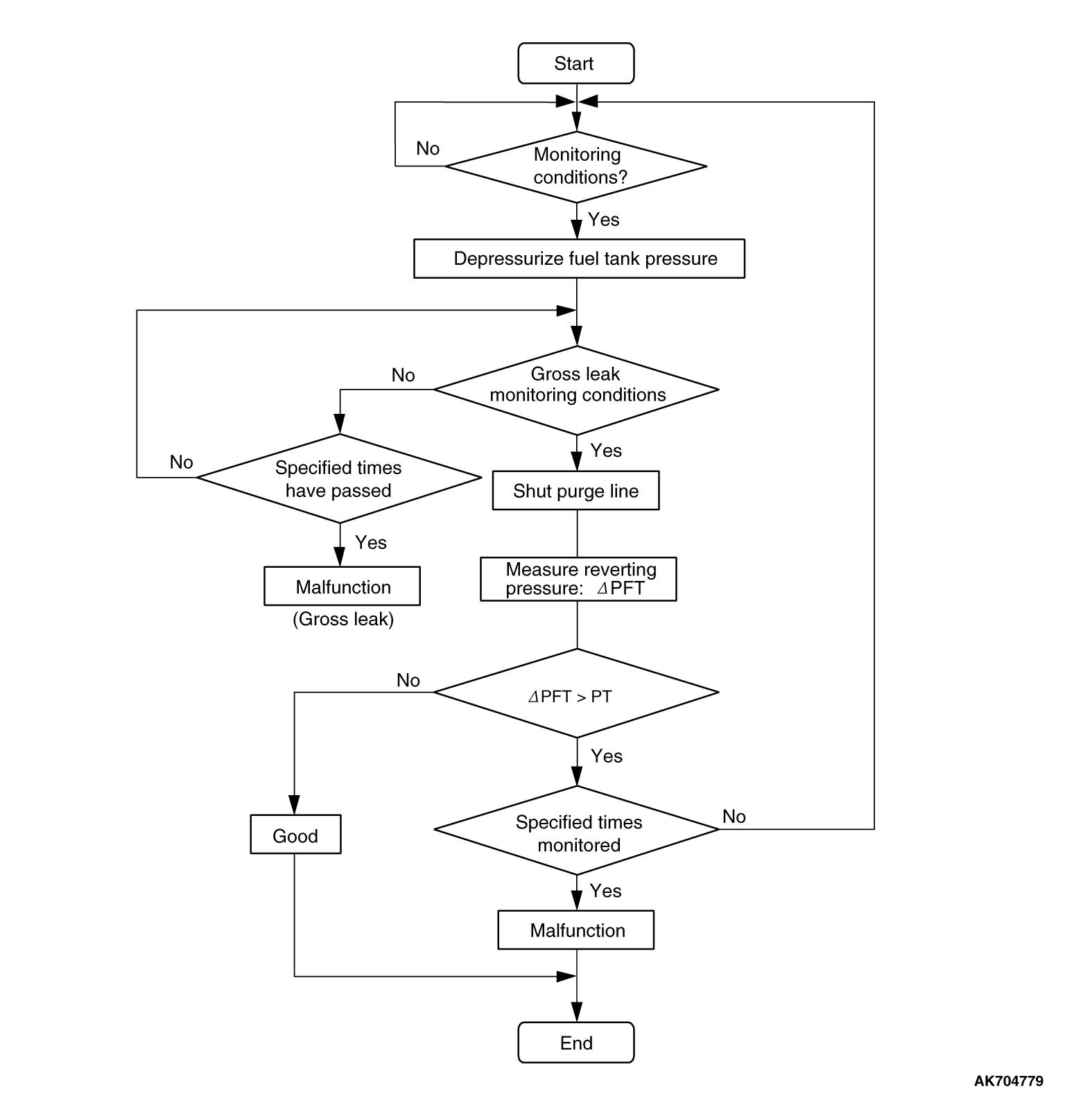
DESCRIPTIONS OF MONITOR METHODS
- Depressurizing EVAP system by intake manifold negative pressure is impossible
within specified period.
MONITOR EXECUTION
MONITOR EXECUTION CONDITIONS (OTHER MONITOR AND SENSOR)
Other Monitor (There is no temporary DTC stored in memory for the item monitored
below)
Sensor (The sensors below are determined to be normal)
DTC SET CONDITIONS
Logic Flow Chart (Monitor Sequence)
DTC SET CONDITIONS
Check Conditions
- Engine coolant temperature is 36°C (97°F) or less when the engine is
started.
- Engine coolant temperature is higher than 60°C (140°F). <Amount of
remaining fuel is 15 - 40 percent of capacity>
- Engine coolant temperature is higher than 20°C (67°F). <Amount
of remaining fuel is 40 - 85 percent of capacity>
- Intake air temperature is 36°C (97°F) or less when the engine
is started.
- Volumetric efficiency is between 20 and 80 percent.
- Engine speed is 1,594 r/min or higher.
- When the evaporative emission purge solenoid and evaporative emission ventilation
solenoid are closed, the pressure in the fuel tank is less than 451 Pa (0.13 in.Hg). <Amount
of remaining fuel is 15 - 40 percent of capacity>
- When the evaporative emission purge solenoid and evaporative emission ventilation
solenoid are closed, the pressure in the fuel tank is less than 324 Pa (0.09 in.Hg). <Amount
of remaining fuel is 40 - 85 percent of capacity>
- Barometric pressure is higher than 76 kPa (22.4 in.Hg).
- Intake air temperature is higher than 5°C (41°F).
- Fuel tank temperature is higher than 36°C (97°F).
- Fuel tank differential pressure sensor output voltage is 1.0 - 4.0 volts.
- At least 10 seconds have passed since the last monitor was complete.
Judgment Criterion
- The fuel tank internal pressure is 1961 Pa (0.284 psi) or more after the evaporative emission
purge solenoid valve has been driven when the fuel tank and vapor line were closed.
OBD-II DRIVE CYCLE PATTERN
Refer to Diagnostic Function - OBD-ll Drive Cycle - Pattern 5  .
.
TROUBLESHOOTING HINTS (THE MOST LIKELY CAUSES FOR THIS CODE TO BE SET ARE:)
- Loose fuel cap.
- Fuel cap relief pressure is incorrect.
- Fuel overflow limiter valve failed.
- Purge line or vapor line is clogged.
- Fuel tank, purge line or vapor line seal failed.
- Evaporative emission purge solenoid valve failed.
- Evaporative emission ventilation solenoid valve failed.
- Fuel tank differential pressure sensor failed.
- Evaporative emission canister seal is faulty.
- Evaporative emission canister is clogged.
|
|
Required Special Tools:
- MB991958: Scan Tool (M.U.T.-III Sub Assembly)
- MB991824: V.C.I.
- MB991827: M.U.T.-III USB Cable
- MB991910: M.U.T.-III Main Harness A
|
|
|
STEP 1. Using scan tool MB991958, check the evaporative
emission system monitor test.
|

|
| caution |
- To prevent damage to scan tool MB991958, always turn the ignition switch
to the "LOCK" (OFF) position before connecting or disconnecting scan tool MB991958.
- During this test, the ECM will automatically increase the engine speed to 1,600
r/min or greater. Check that the transaxle is set to "P" position.
|
(1)Connect scan tool MB991958 to the data link connector.
(2)Turn the ignition switch to the "ON" position.
(3)Erase the DTCs using scan tool MB991958.
(4)Check that the fuel cap is securely closed (Tighten until three clicks are heard).
(5)Start the engine.
(6)Select "System Test."
(7)Select "Evap Leak Mon."
(8)During this test, keep the accelerator pedal at the idle position.
(9)Keep the engine speed and engine load within the specified range. When the monitor
test starts, the "In Progress" item on scan tool MB991958 will change from "NO" to "YES".
(10) Turn the ignition switch to the "LOCK" (OFF) position, and disconnect scan tool MB991958.
Q.
Is "Evap Leak Mon. Completed. Test Failed and DTCs Set" displayed on scan tool MB991958?
 A malfunction has been detected during the monitor test. Refer to the Diagnostic
Trouble Code Chart and diagnose any other DTCs that are set .
If no other DTC’s have been set, go to Step 2 . A malfunction has been detected during the monitor test. Refer to the Diagnostic
Trouble Code Chart and diagnose any other DTCs that are set .
If no other DTC’s have been set, go to Step 2 .
NO <"Evap Leak Mon. Completed. Test Passed" is displayed on scan tool MB991958.> : The evaporative emission system is working properly at this time. Explain to the customer
that an improperly tightened fuel cap can cause the MIL to illuminate. Return the vehicle to
the customer.
NO <"Evap Leak Mon. Discontinued. Retest again from the first" is displayed on scan
tool MB991958.> : The EVAP monitor has been interrupted during the test. Turn the ignition switch
to the "LOCK" (OFF) position once, and repeat the monitoring from Step 1 . : The EVAP monitor has been interrupted during the test. Turn the ignition switch
to the "LOCK" (OFF) position once, and repeat the monitoring from Step 1 .
|
|
|
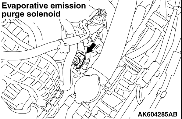
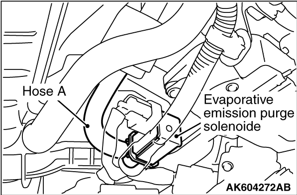
STEP 2. Check the evaporative emission purge solenoid for leaks.
|
|
|
(1)Disconnect hose A from the evaporative emission purge solenoid.
|
|
(2)Connect the hose of the hand pump (pressure-application type) to the chamber side nipple
of the evaporative emission purge solenoid.
(3)Use the hand pump (pressure-application type) to confirm that the evaporative emission
purge solenoid holds vacuum.
(4)Connect hose A to the evaporative emission purge solenoid.
Q.
Does the evaporative emission purge solenoid hold pressure?
Go to Step 3 .
 Replace the evaporative emission purge solenoid. Then go to Step 13 . Replace the evaporative emission purge solenoid. Then go to Step 13 .
|
|
|
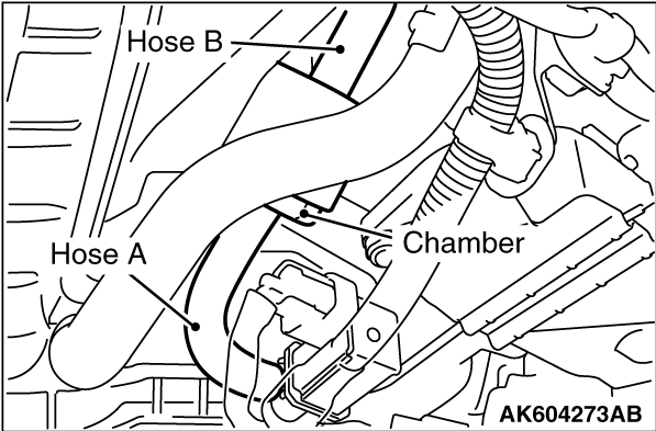
STEP 3. Check for leaks in evaporative emission hose
A, chamber and hose B.
|
|
(1)Use a hand vacuum pump to check hose A, chamber and hose B.
Q.
Do the hoses and chamber hold vacuum?
Go to Step 4 .
Replace any damaged hose or chamber. Then go to Step 13 .
|
|
|
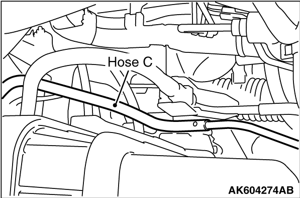
STEP 4. Check for leaks in evaporative emission hose
C.
|
|
(1)Use a hand vacuum pump to check hose C.
Q.
Does hose C hold vacuum?
Go to Step 5 .
Replace any damaged hose. Then go to Step 13 .
|
|
|
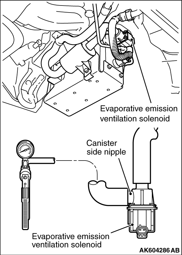
STEP 5. Using scan tool MB991958, check actuator test item 15: Evaporative
emission ventilation solenoid.
|
|
|
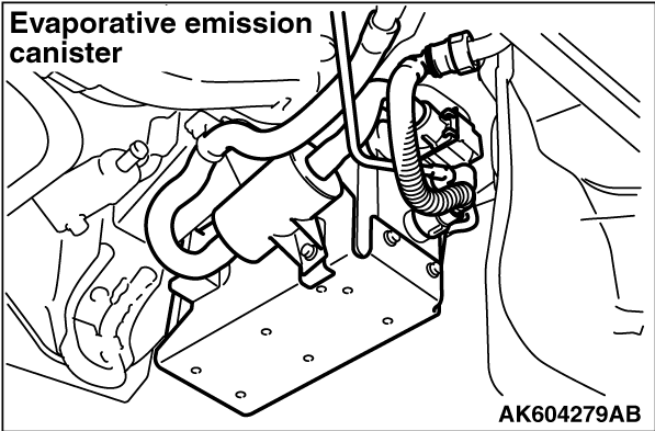
(1)Remove the canister cover.
|
|
|
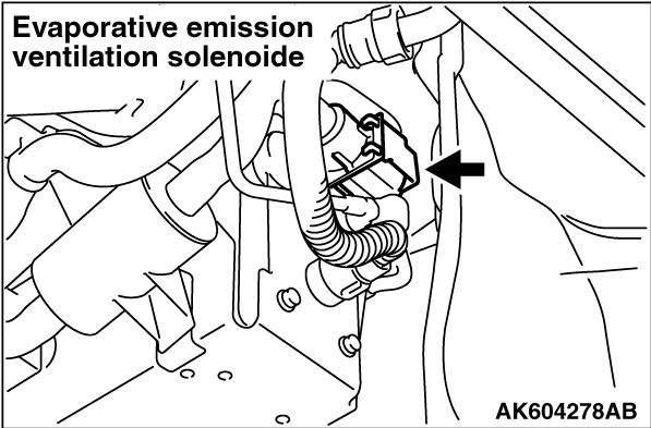
(2)Remove the evaporative emission ventilation solenoid. Do not disconnect the connector.
|
|
(3)Connect the hose of the hand vacuum pump to the canister side nipple of the evaporative
emission ventilation solenoid.
(4)Turn the ignition switch to the "ON" position.
(5)Set scan tool MB991958 to actuator testing mode for item 15: Evaporative Emission
Ventilation Solenoid.
- While the evaporative emission ventilation solenoid is energized, operate
the hand vacuum pump and confirm that the solenoid holds vacuum.
(6)Turn the ignition switch to the "LOCK" (OFF) position.
(7)Disconnect the hand vacuum pump, and reinstall the evaporative emission ventilation solenoid.
(8)Reinstall the canister cover.
Q.
Did the evaporative emission ventilation solenoid hold vacuum?
Go to Step 6 .
Replace the evaporative emission ventilation solenoid. Then go to Step 13 .
|
|
|
STEP 6. Perform the pressure test on the evaporative emission system.
|
|
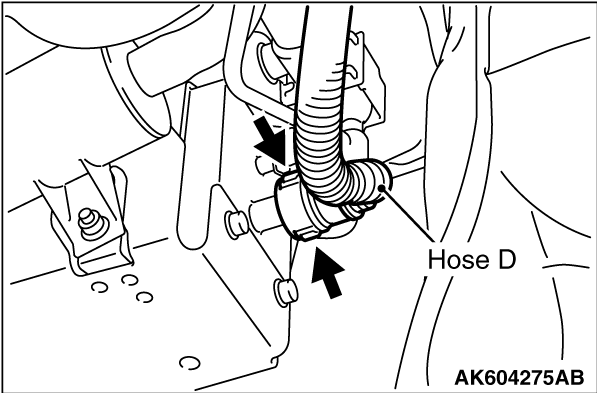
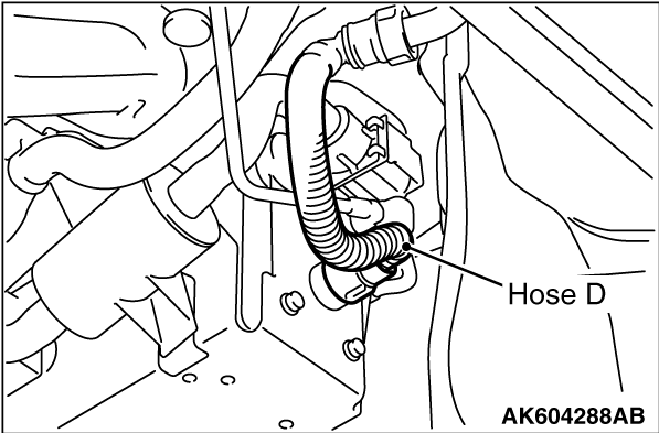
(1)Disconnect hose D from the canister while holding the release buttons indicated in the
illustration pressed by fingers.
|
|
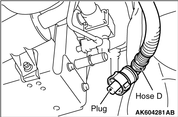
(2)Plug the disconnected end of hose D.
(3)Confirm that the evaporative emission system pressure pump (Miller number 6872A)
is operating properly. Perform the self-test as described in the pump manufacturer’s
instructions.
(4)Remove the fuel cap.
|
|
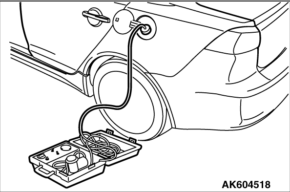
(5)Connect the evaporative emission system pressure pump (Miller number 6872A) to the fuel
tank filler tube by using fuel tank adapter (MLR-8382).
(6)Pressure test the system to determine whether any leaks are present.
| note |
The "Pressure test" in this procedure refers to the I/M240 Simulation Test. The eight
steps of this test are described in the manufacturer’s instructions for the evaporative
emission system pressure pump, Miller number 6872A.
|
(7)Remove the evaporative emission system pressure pump (Miller number 6872A) and
the fuel tank adapter (MLR-8382), and reinstall the fuel cap.
(8)Connect hose D to the evaporative emission canister.
Q.
Is the evaporative emission system line free of leaks?
Go to Step 11 .
Go to Step 7 .
|
|
|
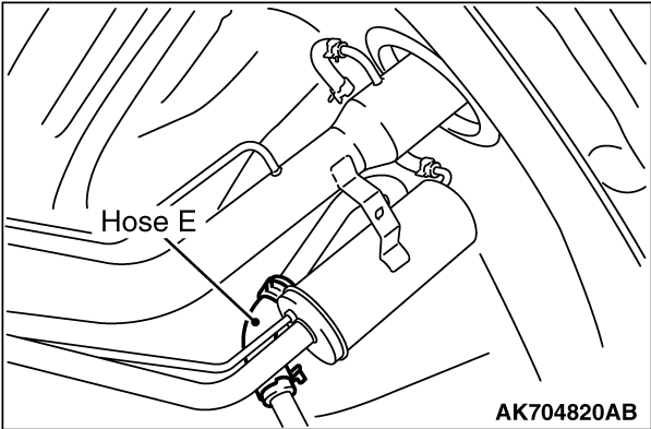
STEP 7. Check for leaks in evaporative emission hoses D through E.
|
|
(1)Use a hand vacuum pump to test each hose from hose D to hose E.
Q.
Do the hoses hold vacuum?
Go to Step 8.
Replace any damaged hose. Then go to Step 13 .
|
|
|
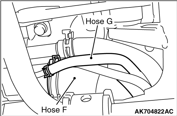
STEP 8. Check for leaks in evaporative emission hoses F and G.
|
|
|
(1)Remove the fuel tank assembly.
|
|
(2)Use a hand vacuum pump to test each hose F and G.
Q.
Do the hoses hold vacuum?
Go to Step 9 .
Replace any damaged hose. Then go to Step 13 .
|
|
|
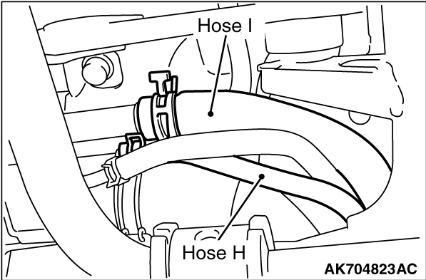
STEP 9. Check for leaks in evaporative emission hoses H and I.
|
|
|
(1)Remove the fuel tank assembly.
|
|
(2)Use a hand vacuum pump to test each hose H and I.
Q.
Does the hose hold vacuum?
Go to Step 10 .
Replace the hose and reinstall the fuel tank assembly. Then go to Step 13 .
|
|
|
STEP 10. Check for leaks in the fuel tank.
|
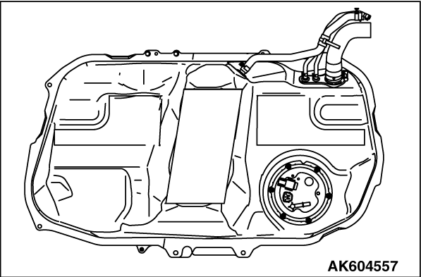
|
(1)Visually check for cracks or other leaks in the fuel tank.
| note |
Carefully check the fuel pump module and the fuel tank differential pressure sensor installation
in the fuel tank.
|
|
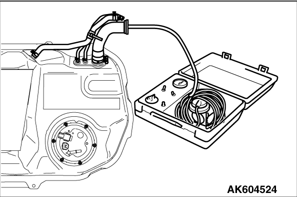
|
(2)Connect the evaporative emission system pressure pump (Miller number 6872A) to the fuel
filler hose.
|
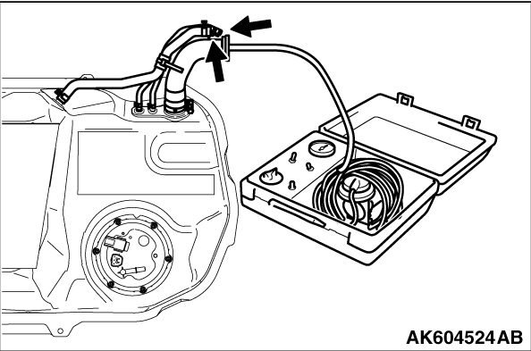
|
(3)Plug the hose and the nipple shown in the illustration.
| note |
If these items are not securely plugged now, the fuel could leak in the next step.
|
(4)Pressurize the fuel tank with the evaporative emission system pressure pump.
(5)In the pressurized state, check for leaks by applying a soapy water solution to
each section and look for bubbles.
Q.
Are any leaks found?
YES <When there is a leak from the attachment points of the fuel pump module, fuel
tank differential pressure sensor, fuel level sensor or leveling valve.> : Repair or replace the leaked parts and check again that there are no leaks. Then reinstall
the fuel tank. Then go to Step 13 .
YES <When there is a leak from the fuel tank.> : Replace the fuel tank. Go to Step 13 .
When there is no leak, reinstall the fuel tank. Then go to Step 11 .
|
|
|
STEP 11. Check the evaporative emission canister for vacuum leaks.
|
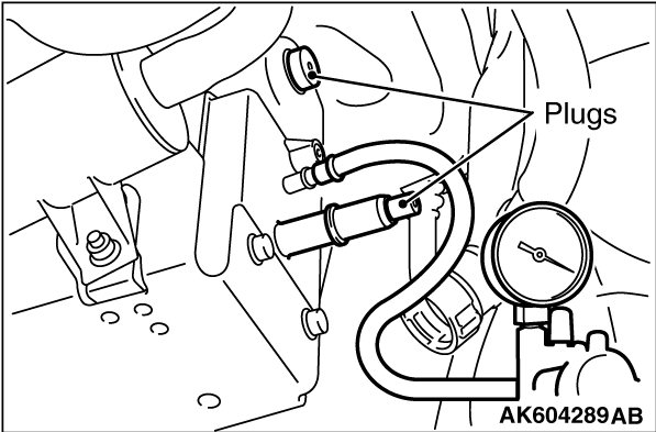
|
(1)Connect a hand vacuum pump to the evaporative emission canister and plug the other nipples.
(2)Apply a pressure on the hand vacuum pump, and confirm that air is maintained.
(3)Disconnect the hand vacuum pump and remove the plugs.
Q.
Is the evaporative emission canister in good condition?
Go to Step 12 .
Replace the evaporative emission canister. Then go to Step 13 .
|
|
|
STEP 12. Using scan tool MB991958, check the evaporative emission
system monitor test.
|
|
|
| caution |
- During this test, the ECM automatically increases
the engine speed to 1,600 r/min or greater. Check that the transaxle is set to "P"
position.
|
|
|
|
(1)Turn the ignition switch to the "ON" position.
|
|
|
(2)Erase the DTCs using scan tool MB991958.
|
|
|
(3)Check that the fuel cap is securely closed (Tighten until three clicks are heard).
|
|
|
(6)Select "Evap Leak Mon."
|
|
|
(7)During the test, keep the accelerator pedal at the idle position.
|
|
|
(8)Keep the engine speed and engine load within the specified range. When the monitor
test starts, the "In Progress" item on scan tool MB991958 will change from "NO" to "YES".
|
|
|
(9)Turn the ignition switch to the "LOCK" (OFF) position.
|
|
|
Q.
Is "Evap Leak Mon. Completed. Test Failed and DTCs Set" displayed on scan tool MB991958?
|
|
|
Replace the ECM. When the ECM is replaced, register the ID code. Refer to GROUP
42B, Diagnosis - ID Code Registration Judgment Table <Vehicles with KOS> or
GROUP 42C, Diagnosis - ID Code Registration Judgment Table <Vehicles with WCM> .
Then go to Step 13 .
|
|
|
|
|
|
NO <"Evap Leak Mon. Completed. Test Passed" is displayed on scan tool MB991958.> : The evaporative emission system is working properly at this time. Go to Step 13
.
|
|
|
|
|
|
NO <"Evap Leak Mon. Discontinued. Retest again from the first" is displayed on scan
tool MB991958.> : The EVAP monitor has been interrupted during the test. Turn the ignition switch
to the "LOCK" (OFF) position once, and repeat the monitoring from Step 13 .
|
|
|
|
|
|
STEP 13. Perform the OBD-II drive cycle.
|
|
|
(1)Confirm the repair by performing the appropriate drive cycle (Refer to Diagnostic
Function - OBD-ll Drive Cycle - Pattern 5 ).
|
|
|
Retry the troubleshooting.
|
|
|
|
|
|
The inspection is complete.
|
|
|
|
)
)
)
)
)
)
)
)
)
)
)
)
)
)
)
)
)
)
)
)
)