|
|
Required Special Tools:
- MB991958: Scan Tool (M.U.T.-III Sub Assembly)
- MB991824: V.C.I.
- MB991827: USB Cable
- MB991910: Main Harness A
|
|
|
Refer to GROUP 54A, Battery - On-vehicle Service - Battery Test  . .
|
|
|
Q.
Are there any abnormalities?
|
|
|
 Replace the battery. Then go to Step 11. Replace the battery. Then go to Step 11.
|
|
|
|
|
|
Q.
Is the harness connector in good condition?
|
|
|
 Repair or replace it. Refer to GROUP 00E, Harness Connector Inspection .
Then go to Step 11. Repair or replace it. Refer to GROUP 00E, Harness Connector Inspection .
Then go to Step 11.
|
|
|
|
|
|
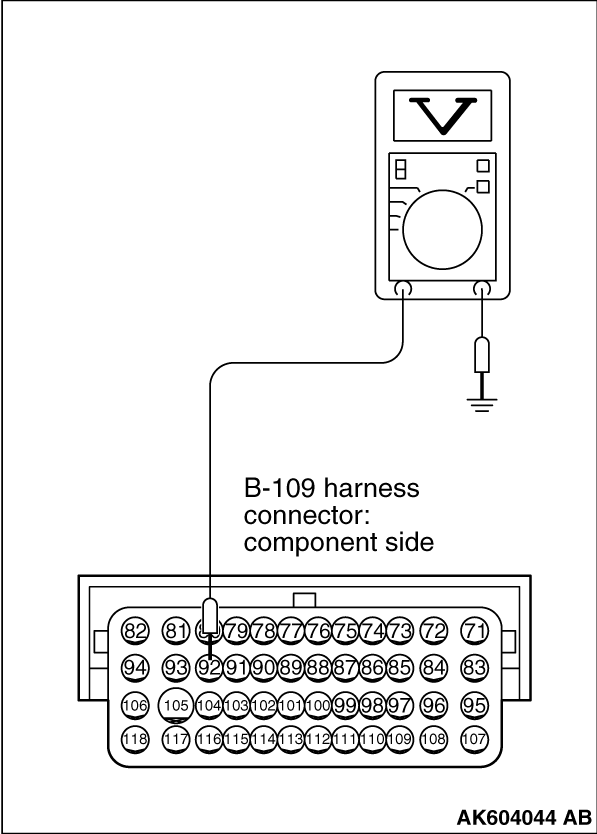
(1)Disconnect the connector B-109 and measure at the harness side.
|
|
|
(2)Turn the ignition switch to the "ON" position.
|
|
(3)Measure the voltage between terminal No. 92 and ground.
- Voltage should be battery positive voltage.
(4) Turn the ignition switch to the "LOCK" (OFF) position.
Q.
Is battery positive voltage (approximately 12 volts) present?
Go to Step 5.
Go to Step 4.
|
|
|
Q.
Is the harness connector in good condition?
|
|
|
Repair harness wire between ETACS-ECU connector C-304 (terminal No. 10) and ECM
connector B-109 (terminal No. 92) because of open circuit or short circuit to ground. Then go
to Step 11.
|
|
|
|
|
|
Repair or replace it. Refer to GROUP 00E, Harness Connector Inspection .
Then go to Step 11.
|
|
|
|
|
|
Q.
Is the harness connector in good condition?
|
|
|
Repair or replace it. Refer to GROUP 00E, Harness Connector Inspection .
Then go to Step 11.
|
|
|
|
|
|
Q.
Is the harness wire in good condition?
|
|
|
Repair it. Then go to Step 11.
|
|
|
|
|
|
Q.
Is the harness connector in good condition?
|
|
|
Repair or replace it. Refer to GROUP 00E, Harness Connector Inspection .
Then go to Step 11.
|
|
|
|
|
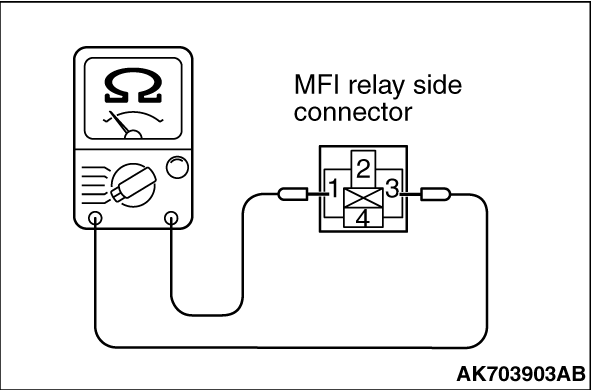
(2)Check for continuity between the MFI relay terminals No. 1 and No. 3.
- There should be continuity.
|
|
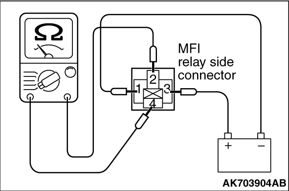
(3)Use jumper wires to connect MFI relay terminal No. 3 to the positive battery terminal
and terminal No. 1 to the negative battery terminal.
(4)Check for continuity between the MFI relay terminals No. 4 and No. 2 while connecting
and disconnecting the jumper wire at the negative battery terminal.
- Continuity (2 ohms or less) <Negative battery terminal connected>
- Should be open loop <Negative battery terminal disconnected>
(5)Install the MFI relay.
Q.
Is the measured resistance within the specified range?
Go to Step 9.
Replace the MFI relay. Then go to Step 11.
|
|
|
Q.
Is the harness wire in good condition?
|
|
|
Repair it. Then go to Step 11.
|
|
|
|

|
| caution |
To prevent damage to scan tool MB991958, always turn the ignition switch to
the "LOCK" (OFF) position before connecting or disconnecting scan tool MB991958.
|
(1)Connect scan tool MB991958 to the data link connector.
(2)Turn the ignition switch to the "ON" position.
(3)After the DTC has been deleted, read the DTC again.
(4)Turn the ignition switch to the "LOCK" (OFF) position.
Q.
Is DTC P0606 set?
Replace the ECM. When the ECM is replaced, register the ID code. Refer to GROUP
42B, Diagnosis - ID Code Registration Necessity Judgment Table <Vehicles with KOS> or
GROUP 42C, Diagnosis - ID Codes Registration Judgment Table <Vehicles with WCM> .
Then go to Step 11.
It can be assumed that this malfunction is intermittent. Refer to GROUP 00, How
to Use Troubleshooting/ Inspection Service Points - How to Cope with Intermittent Malfunctions .
|
|
| caution |
To prevent damage to scan tool MB991958, always turn the ignition switch to
the "LOCK" (OFF) position before connecting or disconnecting scan tool MB991958.
|
(1)Connect scan tool MB991958 to the data link connector.
(2)Turn the ignition switch to the "ON" position.
(3)After the DTC has been deleted, read the DTC again.
(4)Turn the ignition switch to the "LOCK" (OFF) position.
Q.
Is DTC P0606 set?
Retry the troubleshooting.
The inspection is complete.
|
![[Previous]](../../../buttons/fprev.png)
![[Next]](../../../buttons/fnext.png)
)
)
)
)
)
)
)