![[Previous]](../../../buttons/fprev.png)
![[Next]](../../../buttons/fnext.png)
DTC P0420: Warm
Up Catalyst Efficiency Below Threshold
TECHNICAL DESCRIPTION
- The signal from the heated oxygen sensor (rear) differs
from the heated oxygen sensor (front), because the catalytic converter purifies exhaust gas.
When the catalytic converter has deteriorated, the signal from the heated oxygen sensor (front)
becomes similar to the heated oxygen sensor (rear).
- The ECM compares the output of the heated oxygen sensor (front and rear) signals.
DESCRIPTIONS OF MONITOR METHODS
Heated oxygen sensor (front and rear) rich/lean switching
frequencies are nearly equal.
MONITOR EXECUTION
MONITOR EXECUTION CONDITIONS (Other monitor and Sensor)
Other Monitor (There is no temporary DTC stored in memory
for the item monitored below)
- Heated oxygen sensor (front) monitor
- Heated oxygen sensor (rear) monitor
- Heated oxygen sensor (front) heater monitor
- Heated oxygen sensor (rear) heater monitor
- Heated oxygen sensor (front) inactive monitor
- Heated oxygen sensor offset voltage monitor
- Misfire monitor
- Fuel system monitor
- Air/fuel ratio feedback monitor
Sensor (The sensor below is determined to be normal)
- Mass airflow sensor
- Engine coolant temperature sensor
- Intake air temperature sensor
- Barometric pressure sensor
- Throttle position sensor
- Accelerator pedal position sensor
DTC SET CONDITIONS
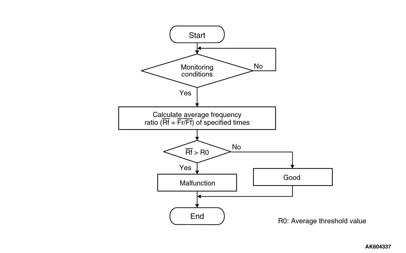
Logic Flow Chart
Check Conditions
- Engine speed is less than 3,500 r/min.
- Accelerator pedal is depressed.
- Mass airflow rate is between 13 and 45 g/sec.
- More than 3 seconds have passed after the above-mentioned three conditions have
been met.
- Intake air temperature is more than -10°C (14°F).
- Barometric pressure is more than 76 kPa (22.4 in.Hg).
- Under the closed loop air/fuel ratio control.
- Vehicle speed is more than 1.5 km/h (1.0 mph).
- The ECM monitors the maximum 5 times per drive cycle under these conditions.
- Short-term fuel trim is between -20 percent and +17 percent.
- The cumulative mass airflow is more than 1,638 g.
Judgement Criterion
- When the monitoring for 10 seconds is carried out 5 times, the frequency ratio of
rear and front signals is more than the specified value.
| note |
The specified value varies depending on the average air flow rate.
|
FAIL-SAFE AND BACKUP FUNCTION
OBD-II DRIVE CYCLE PATTERN
Refer to Diagnostic Function -
OBD-II Drive Cycle -
Pattern
3  .
.
TROUBLESHOOTING HINTS (The most likely causes for this code to be set are:)
- Catalytic converter deteriorated.
- Heated oxygen sensor failed.
- Exhaust leak.
- ECM failed.
|
|
Required Special Tools:
- MB991958: Scan Tool (M.U.T.-III Sub Assembly)
- MB991824: V.C.I.
- MB991827: USB Cable
- MB991910: Main Harness A
|
|
|
STEP 1. Replace the catalytic converter.
|
|
|
(1)Replace the catalytic converter.
|
|
|
(2)Carry out a test drive with the drive cycle pattern. Refer to Diagnostic Function -
OBD-II
Drive Cycle -
Pattern 3 .
|
|
|
(3)Check the diagnostic trouble code (DTC).
|
|
|
 Replace the ECM. When the ECM is replaced, register the ID code. Refer to GROUP
42B, Diagnosis -
ID Code Registration Necessity Judgment Table <Vehicles with KOS> or
GROUP 42C, Diagnosis -
ID Codes Registration Judgment Table <Vehicles with WCM> . Replace the ECM. When the ECM is replaced, register the ID code. Refer to GROUP
42B, Diagnosis -
ID Code Registration Necessity Judgment Table <Vehicles with KOS> or
GROUP 42C, Diagnosis -
ID Codes Registration Judgment Table <Vehicles with WCM> .
|
|
|
|
|
|
 The inspection is complete. The inspection is complete.
|
|
|
|
)