![[Previous]](../../../buttons/fprev.png)
![[Next]](../../../buttons/fnext.png)
DTC U0141: ETACS-ECU
Time-out
| caution |
- If the ECM output the
DTC U0141, make sure to diagnose the CAN bus line.
- Before replacing the ECU, make sure that the communication circuit is operating
normally.
|
DESCRIPTIONS OF MONITOR METHODS
There is no data from ETACS-ECU for the specified time. (ETACS-ECU also detect communication
error with ECM.)
MONITOR EXECUTION
MONITOR EXECUTION CONDITIONS (Other monitor and Sensor)
Other Monitor (There is no temporary DTC stored in memory
for the item monitored below)
Sensor (The sensor below is determined to be normal)
DTC SET CONDITIONS
Logic Flow Chart
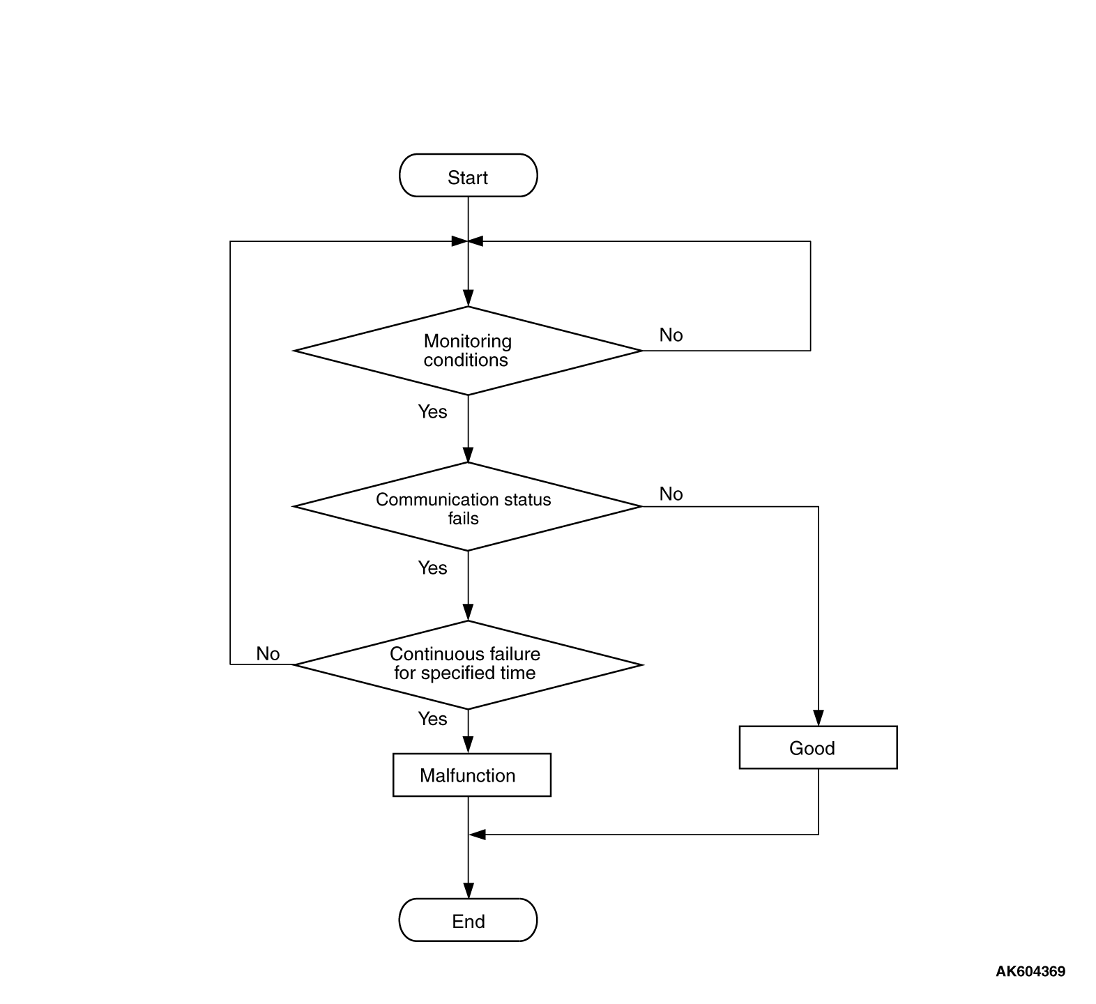
Check Condition
- Battery positive voltage is between 10 and 16.5 volts.
Judgement Criterion
- Unable to receive ETACS-ECU signals through the CAN bus line for 4 seconds.
COMMENT
Current Trouble
- Some of the possible causes are a harness or connector damage between the ECM and
the ETACS-ECU on the CAN bus line, a failure in the ETACS-ECU power supply system, a failure
in the ETACS-ECU, or a failure in the ECM.
Past Trouble
- Proceed to troubleshoot based on a harness or connector damage on the CAN bus line
between the ECM and ETACS-ECU, and a failure in the ETACS-ECU power supply system. Refer to "How
to cope with past trouble" (Refer to GROUP 00, How to Use Troubleshooting/Inspection Service
Points - How to Treat Past Trouble
 ).
).
| note |
If a malfunction occurred in the past, a failure cannot be discovered through the MB991958
CAN bus diagnosis even if there might be a problem with the CAN bus. In this case, refer to
GROUP 00, How to Use Troubleshooting/Inspection Service Points - How to Cope with Intermittent
Malfunctions . Furthermore, it is possible to narrow down the
areas of the possible failures from the DTCs that are output by the ECUs, which are communicating on
the CAN bus [Refer to GROUP 54C, Explanation about the Scan Tool (M.U.T.-III) CAN Bus Diagnostics ].
|
FAIL-SAFE AND BACKUP FUNCTION
OBD-II DRIVE CYCLE PATTERN
None.
TROUBLESHOOTING HINTS (The most likely causes for this code to be set are:)
- CAN line harness damage or connector damage.
- ETACS-ECU failed.
- ECM failed.
|
|
Required Special Tools:
- MB991958: Scan Tool (M.U.T.-III Sub Assembly)
- MB991824: V.C.I.
- MB991827: USB Cable
- MB991910: Main Harness A
|
|
|
STEP 1. Using scan tool MB991958, diagnose CAN bus line.
|

|
| caution |
To prevent damage to scan tool MB991958, always turn the ignition switch to the "LOCK"
(OFF) position before connecting or disconnecting scan tool MB991958.
|
(1)Connect scan tool MB991958 to the data link connector.
(2)Turn the ignition switch to the "ON" position.
(3)Diagnose CAN bus line.
(4)Turn the ignition switch to the "LOCK" (OFF) position.
Q.
Is the CAN bus line normal?
 Go to Step 2. Go to Step 2.
 Repair the CAN bus line. Refer to GROUP 54C, Diagnosis - CAN Bus Diagnostics
Table . Then go to Step 6. Repair the CAN bus line. Refer to GROUP 54C, Diagnosis - CAN Bus Diagnostics
Table . Then go to Step 6.
|
|
|
STEP 2. Using scan tool MB991958, read the diagnostic trouble code
(DTC).
|
|
|
(1)Turn the ignition switch to the "ON" position.
|
|
|
(3)Turn the ignition switch to the "LOCK" (OFF) position.
|
|
|
Refer to GROUP 54A, ETACS - Diagnostic Trouble Code Chart .
|
|
|
|
|
|
Go to Step 3.
|
|
|
|
|
|
STEP 3. Using scan tool MB991958, read the diagnostic trouble code
(DTC).
|
|
|
(1)Turn the ignition switch to the "ON" position.
|
|
|
(2)Read the AWC-DTC, TC-SST-DTC, Shift lever-DTC, ASC-DTC, KOS-DTC or WCM-DTC, SRS-DTC,
Occupant classification-DTC, Combination meter-DTC, CAN box unit-DTC, Satellite radio tuner-DTC,
A/C-DTC and Heater control unit-DTC.
|
|
|
(3)Turn the ignition switch to the "LOCK" (OFF) position.
|
|
|
Go to Step 4.
|
|
|
|
|
|
Go to Step 5.
|
|
|
|
|
|
STEP 4. Using scan tool MB991958, read the diagnostic trouble code
(DTC).
|
|
|
(1)Turn the ignition switch to the "ON" position.
|
|
|
(2)After the MFI-DTC has been deleted, read the MFI-DTC again.
|
|
|
(3)Turn the ignition switch to the "LOCK" (OFF) position.
|
|
|
Replace the ETACS-ECM. Then go to Step 6.
|
|
|
|
|
|
It can be assumed that this malfunction is intermittent of CAN bus line between
ECM and ETACS-ECU. Refer to GROUP 00, How to Use Troubleshooting/Inspection Service Points - How
to Cope with Intermittent Malfunctions .
|
|
|
|
|
|
STEP 5. Using scan tool MB991958, read the diagnostic trouble code
(DTC).
|
|
|
(1)Turn the ignition switch to the "ON" position.
|
|
|
(2)After the MFI-DTC has been deleted, read the MFI-DTC again.
|
|
|
(3)Turn the ignition switch to the "LOCK" (OFF) position.
|
|
|
Replace the ECM. When the ECM is replaced, register the ID code. Refer to GROUP
42B, Diagnosis - ID Code Registration Necessity Judgment Table <Vehicles with KOS> or
GROUP 42C, Diagnosis - ID Codes Registration Judgment Table <Vehicles with WCM> .
Then go to Step 6.
|
|
|
|
|
|
It can be assumed that this malfunction is intermittent of CAN bus line between
ECM and ETACS-ECU. Refer to GROUP 00, How to Use Troubleshooting/Inspection Service Points - How
to Cope with Intermittent Malfunctions .
|
|
|
|
|
|
STEP 6. Using scan tool MB991958, read the diagnostic trouble code
(DTC).
|
|
|
(1)Turn the ignition switch to the "ON" position.
|
|
|
(2)After the MFI-DTC has been deleted, read the MFI-DTC again.
|
|
|
(3)Turn the ignition switch to the "LOCK" (OFF) position.
|
|
|
Retry the troubleshooting.
|
|
|
|
|
|
The inspection is complete.
|
|
|
|
)
)