![[Previous]](../../../buttons/fprev.png)
![[Next]](../../../buttons/fnext.png)
DTC P2423: HC
adsorber (HC trap catalyst) efficiency below threshold <California>
TECHNICAL DESCRIPTION
After the fuel cut-off during the deceleration, the rich control is performed. Depending
on the point of time when the catalyst releases oxygen which is temporarily absorbed by the
lean control, the HC adsorber (HC trap catalyst) within center exhaust pipe is judged on its
deterioration in performance.
DESCRIPTIONS OF MONITOR METHODS
When the difference in the switching time into the rich control is below the specified
time between the heated (rear) oxygen sensor and the heated oxygen sensor (3rd), it is judged
that a malfunction exists.
MONITOR EXECUTION
Once per driving cycle
MONITOR EXECUTION CONDITIONS (Other monitor and Sensor)
Other Monitor (There is no temporary DTC stored in memory
for the item monitored below)
- Heated oxygen sensor (front) monitor
- Heated oxygen sensor (rear) monitor
- Heated oxygen sensor (3rd) monitor
- Heated oxygen sensor heater (front) monitor
- Heated oxygen sensor heater (rear) monitor
- Heated oxygen sensor heater (3rd) monitor
- Misfire monitor
- Fuel system monitor
- Air/fuel ratio feedback monitor
Sensor (The sensor below is determined to be normal)
- Mass airflow sensor
- Engine coolant temperature sensor
- Intake air temperature sensor
- Barometric pressure sensor
- Throttle position sensor
- Accelerator pedal position sensor
DTC SET CONDITIONS
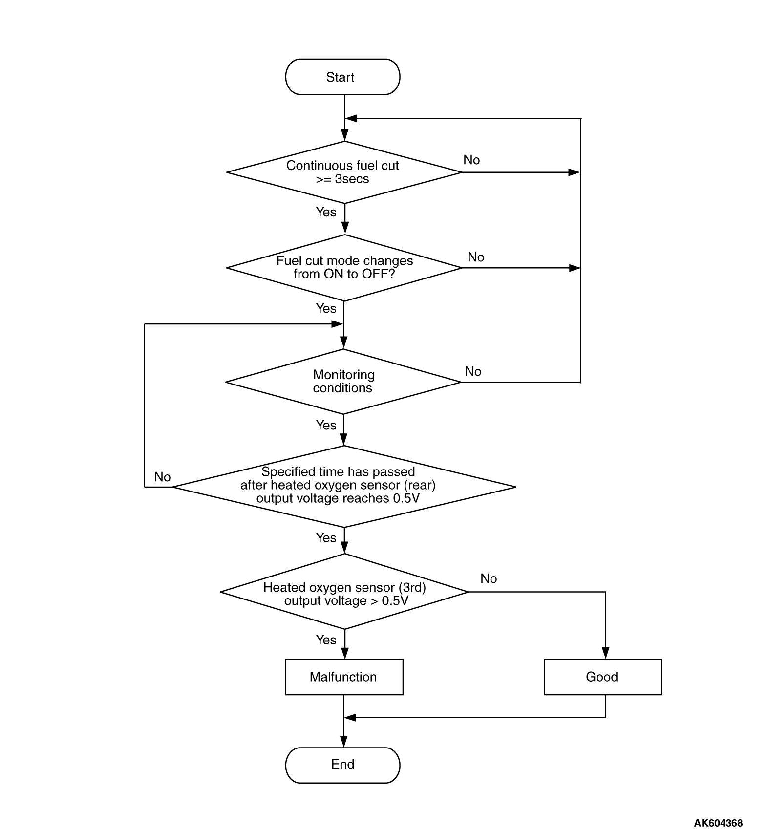
Logic Flow Chart
Check Conditions
- Engine speed is lower than 1,500 r/min <M/T> or 1,313 r/min <CVT>.
- Volumetric efficiency is lower than 25 percent <M/T> or 35 percent <CVT>.
- The throttle valve is closed.
- Barometric pressure is higher than 76 kPa (22.4 in.Hg).
- Intake air temperature is higher than -10°C (14°F).
- The accumulative mass airflow is higher than 2,900 g.
- The fuel shut-off mode continues for 3 seconds or more.
- After the fuel shut-off mode is terminated, the output voltage of the heated oxygen
sensor (3rd) is 0.2 volt or less for 0.5 seconds.
Judgment Criterion
- After the output voltage of the heated oxygen sensor (rear) reaches 0.5 volt, the
output voltage of the heated oxygen sensor (3rd) reaches 0.5 volt within 1.5 seconds.
OBD-II DRIVE CYCLE PATTERN
Refer to Diagnostic Function - OBD-II Drive Cycle - Pattern
11  .
.
TROUBLESHOOTING HINTS (The most likely causes for this code to be set are: )
- HC trap catalyst deterioration within center exhaust
pipe.
- ECM failed.
|
|
Required Special Tools:
- MB991958: Scan Tool (M.U.T.-III Sub Assembly)
- MB991824: V.C.I.
- MB991827: USB Cable
- MB991910: Main Harness A
|
|
|
STEP 1. Replace the center exhaust pipe.
|
|
|
(1)Replace the center exhaust pipe.
|
|
|
(2)Carry out a test drive with the drive cycle pattern. Refer to Diagnostic Function - OBD-II
Drive Cycle - Pattern 11 .
|
|
|
(3)Check the diagnostic trouble code (DTC).
|
|
|
 Replace the ECM. When the ECM is replaced, register the ID code. Refer to GROUP
42B, Diagnosis - ID Code Registration Judgment Table <Vehicles with KOS> or
GROUP 42C, Diagnosis - ID Codes Registration Judgment Table <Vehicles with WCM> . Replace the ECM. When the ECM is replaced, register the ID code. Refer to GROUP
42B, Diagnosis - ID Code Registration Judgment Table <Vehicles with KOS> or
GROUP 42C, Diagnosis - ID Codes Registration Judgment Table <Vehicles with WCM> .
|
|
|
|
|
|
 The inspection is complete. The inspection is complete.
|
|
|
|
)