![[Previous]](../../../buttons/fprev.png)
![[Next]](../../../buttons/fnext.png)
DTC P1241: Torque
Monitor
TECHNICAL DESCRIPTION
Compares the actual torque signal computed from a mass airflow sensor signal with the
driver demand torque signal computed from an accelerator pedal position sensor signal.
MONITOR EXECUTION
MONITOR EXECUTION CONDITIONS (Other monitor and Sensor)
Other Monitor (There is no temporary DTC stored in memory
for the item monitored below)
Sensor (The sensor below is determined to be normal)
DTC SET CONDITIONS
Logic Flow Chart
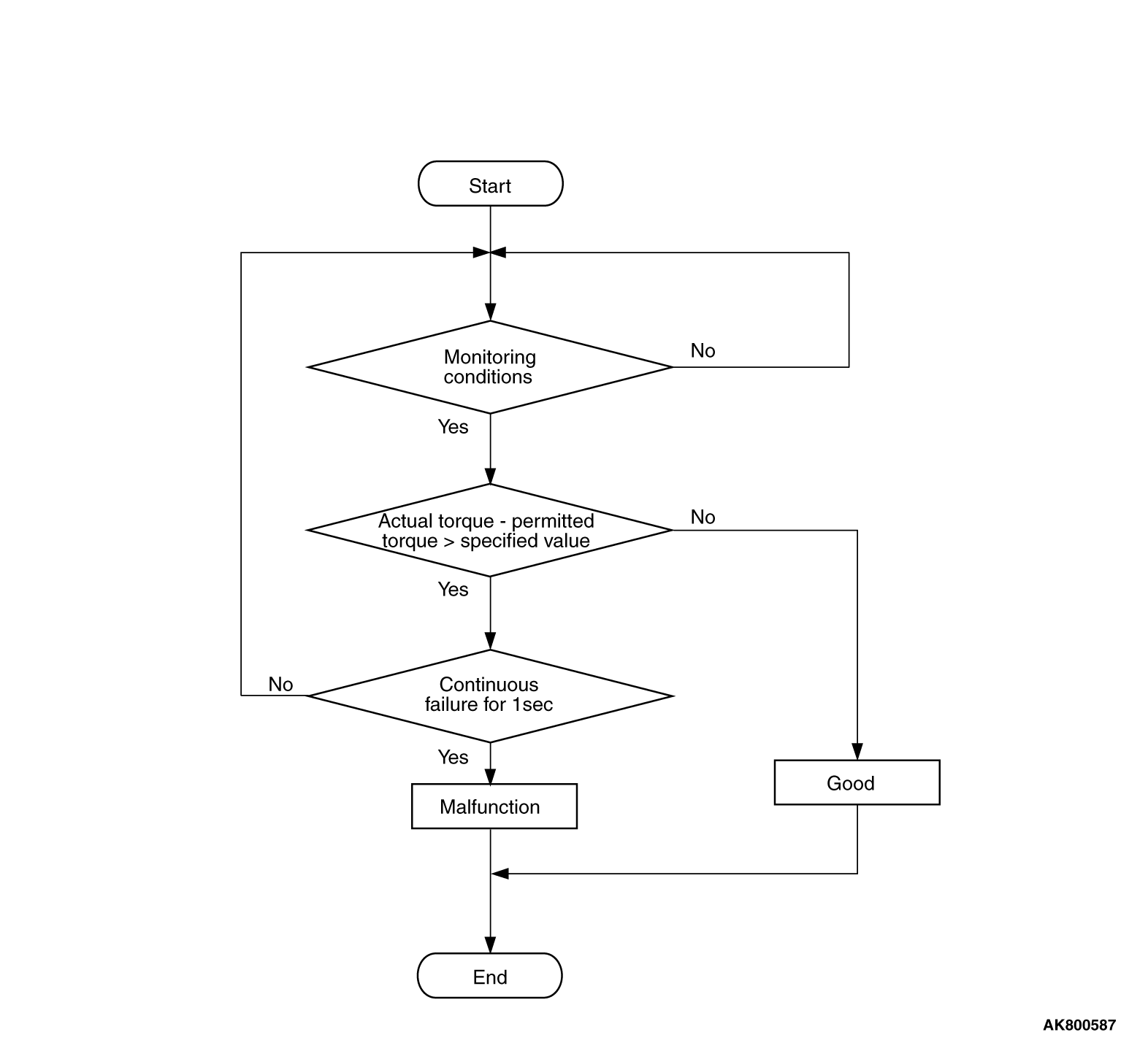
Check Conditions
- Engine speed is more than 500 r/min.
- Volumetric efficiency is more than 16 percent.
Judgement Criterion
- The requested torque signal subtracted from the actual torque signal is more than
130 N·m (96 ft-lb) for 1 second.
FAIL-SAFE AND BACKUP FUNCTION
- Throttle opening degree position is in default position.
OBD-II DRIVE CYCLE PATTERN
Refer to Diagnostic Function -
OBD-II Drive
Cycle -
Pattern 16  .
.
TROUBLESHOOTING HINTS (The most likely causes for this code to be set are:)
- Throttle actuator control motor failed.
- Connector damage.
- Harness damage.
- Intake system vacuum leak.
- There is some contamination around mass airflow sensor.
- Intake charge pressure failed.
- Intake charge pressure control system failed.
- ECM failed.
|
|
Required Special Tools:
- MB991958: Scan Tool (M.U.T.-III Sub Assembly)
- MB991824: V.C.I.
- MB991827: USB Cable
- MB991910: Main Harness A
|
|
|
STEP 1. Using scan tool MB991958, read the diagnostic
trouble code (DTC).
|

|
| caution |
To prevent damage to scan tool MB991958, always turn the ignition switch to the "LOCK"
(OFF) position before connecting or disconnecting scan tool MB991958.
|
(1)Connect scan tool MB991958 to the data link connector.
(2)Turn the ignition switch to the "ON" position.
(3)Read the DTC.
(4)Turn the ignition switch to the "LOCK" (OFF) position.
Q.
Is the diagnostic trouble code other than P1241 set?
 Refer to, Diagnostic Trouble Code Chart . Refer to, Diagnostic Trouble Code Chart .
 Go to Step 2. Go to Step 2.
|
|
|
STEP 2. Using scan tool MB991958, check data list.
|
|
|
(1)Turn the ignition switch to the "ON" position.
|
|
|
(2)Check the following items in the data list. Refer to, Data List Reference Table .
- Item 10: Mass Airflow Sensor.
- Item 11: Accelerator Pedal Position Sensor (main).
- Item 12: Accelerator Pedal Position Sensor (sub).
|
|
|
(3)Turn the ignition switch to the "LOCK" (OFF) position.
|
|
|
Q.
Are they operating properly?
|
|
|
Go to Step 3.
|
|
|
|
|
|
Repair or replace it. Then go to Step 12.
|
|
|
|
|
|
STEP 3. Check for intake system vacuum leak.
|
|
|
Q.
Are there any abnormalities?
|
|
|
Repair it. Then go to Step 12.
|
|
|
|
|
|
Go to Step 4.
|
|
|
|
|
|
STEP 4. Check for foreign matter being around the mass airflow sensor.
|
|
|
Q.
Are there any foreign matter?
|
|
|
Repair it. Then go to Step 12..
|
|
|
|
|
|
Go to Step 5.
|
|
|
|
|
|
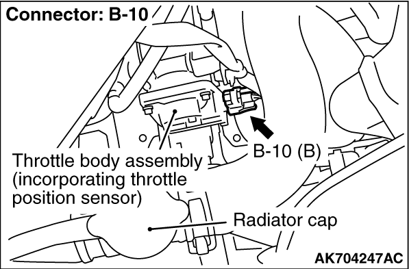
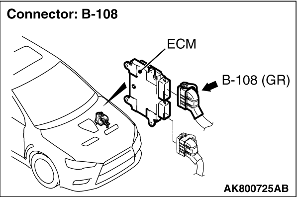
STEP 5. Check harness connector B-10 at throttle actuator control
motor and harness connector B-108 at ECM for damage.
|
|
|
Q.
Are the harness connectors in good condition?
|
|
|
Go to Step 6.
|
|
|
|
|
|
Repair or replace them. Refer to GROUP 00E, Harness Connector Inspection .
Then go to Step 12.
|
|
|
|
|
|
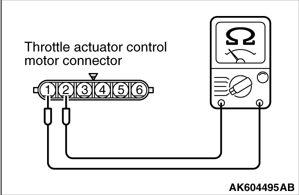
STEP 6. Check the throttle actuator control motor.
|
|
(1)Disconnect the throttle actuator control motor connector B-10.
(2)Measure the resistance between throttle actuator control motor side connector terminal
No. 1 and No. 2.
Standard value: 0.3 -
80 Ω
[at 20°C (68°C)]
Q.
Is the measured resistance between 0.3 and 80 Ω
[at 20°C
(68°C)?
Go to Step 7.
Replace the throttle body assembly. Then go to Step 12.
|
|
|
STEP 7. Check for harness damage between throttle actuator control
motor connector B-10 (terminal No. 1) and ECM connector B-108 (terminal No. 15).
|
|
|
Q.
Is the harness wire in good condition?
|
|
|
Go to Step 8.
|
|
|
|
|
|
Repair it. Then go to Step 12.
|
|
|
|
|
|
STEP 8. Check for harness damage between throttle actuator control
motor connector B-10 (terminal No. 2) and ECM connector B-108 (terminal No. 16).
|
|
|
Q.
Is the harness wire in good condition?
|
|
|
Go to Step 9.
|
|
|
|
|
|
Repair it. Then go to Step 12.
|
|
|
|
|
|
STEP 9. Check the intake charge pressure.
|
|
|
Refer to GROUP 15, On-vehicle Service -
Intake Charge Pressure Check .
|
|
|
Q.
Are there any abnormalities?
|
|
|
Repair it. Then go to Step 12.
|
|
|
|
|
|
Go to Step 10.
|
|
|
|
|
|
STEP 10. Check the intake charge pressure control system.
|
|
|
Refer to GROUP 15, On-vehicle Service -
Intake Charge Pressure Control System
Check .
|
|
|
Q.
Are there any abnormalities?
|
|
|
Repair it. Then go to Step 12.
|
|
|
|
|
|
Go to Step 11.
|
|
|
|
|
|
STEP 11. Check the trouble symptoms.
|
|
|
(1)Carry out a test drive with the drive cycle pattern. Refer to Diagnostic Function -
OBD-II
Drive Cycle -
Pattern 16 .
|
|
|
(2)Check the diagnostic trouble code (DTC).
|
|
|
Replace the ECM. When the ECM is replaced, register the ID code. Refer to GROUP
42B, Diagnosis -
ID Code Registration Necessity Judgment Table <Vehicles with KOS> or GROUP
42C, Diagnosis -
ID Codes Registration Judgment Table <Vehicles with WCM> .
Then go to Step 12.
|
|
|
|
|
|
It can be assumed that this malfunction is intermittent. Refer to GROUP 00, How
to Use Troubleshooting/Inspection Service Points -
How to Cope with Intermittent Malfunctions .
|
|
|
|
|
|
STEP 12. Test the OBD-II drive cycle.
|
|
|
(1)Carry out a test drive with the drive cycle pattern. Refer to Diagnostic Function -
OBD-II
Drive Cycle -
Pattern 16 .
|
|
|
(2)Check the diagnostic trouble code (DTC).
|
|
|
Retry the troubleshooting.
|
|
|
|
|
|
The inspection is complete.
|
|
|
|
)
)
)
)
)