![[Previous]](../../../buttons/fprev.png)
![[Next]](../../../buttons/fnext.png)
DTC P1238: Mass
Airflow Sensor Plausibility (torque monitor)
TECHNICAL DESCRIPTION
Compare the actual measurement of volumetric efficiency by a mass airflow sensor signal
with volumetric efficiency estimated from a throttle position sensor (main or sub) signal.
MONITOR EXECUTION
Continuous
MONITOR EXECUTION CONDITIONS (Other monitor and Sensor)
Other Monitor (There is no temporary DTC stored in memory
for the item monitored below)
Sensor (The sensor below is determined to be normal)
DTC SET CONDITIONS
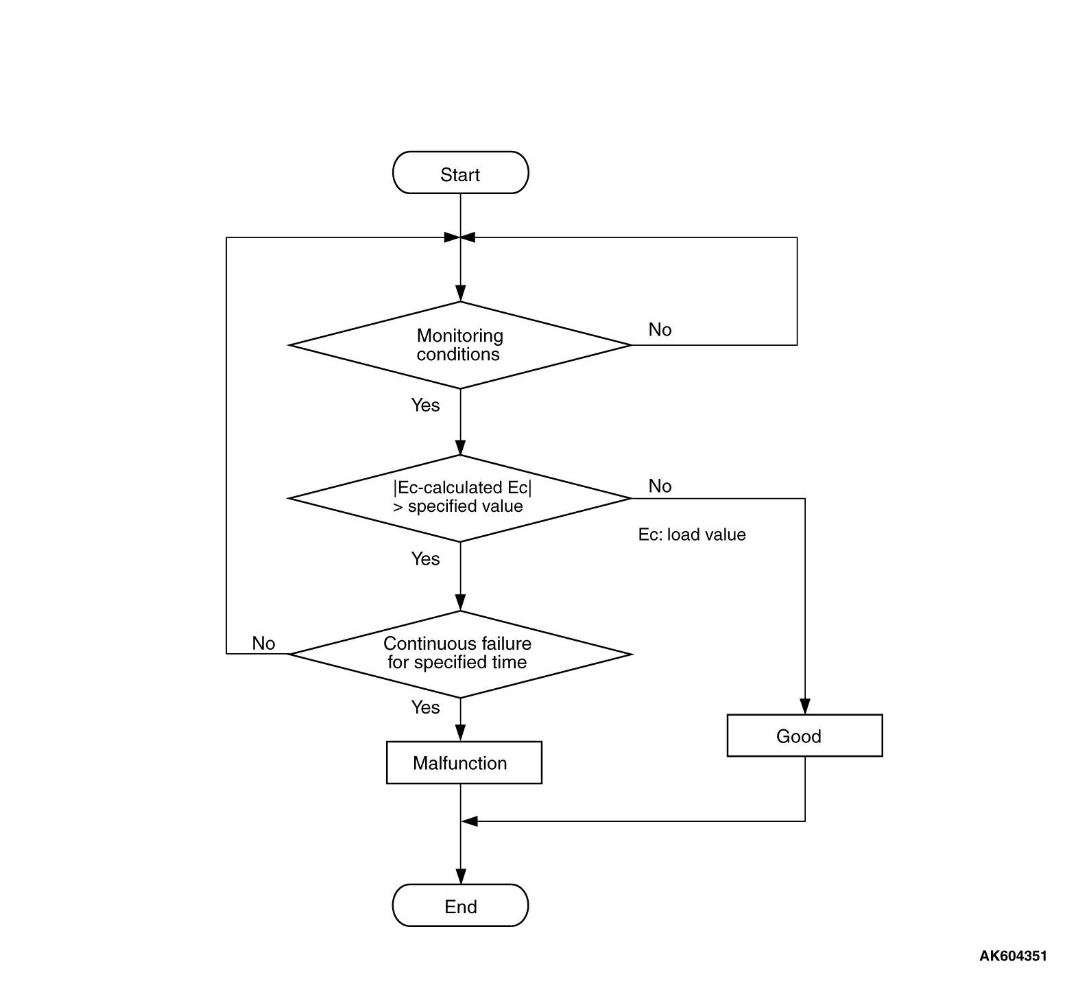
Check Conditions
- Engine speed is more than 750 r/min.
- Except while fuel is being shut off.
Judgment Criterion
- For 0.9 second, the difference between the actual volumetric efficiency and the
volumetric efficiency estimated by the throttle position sensor (main) is more than 45 percent.
Check Conditions
- Engine speed is more than 750 r/min.
- Except while fuel is being shut off.
Judgment Criterion
- For 0.9 second, the difference between the actual volumetric efficiency and the
volumetric efficiency estimated by the throttle position sensor (sub) is more than 45 percent.
FAIL-SAFE AND BACKUP FUNCTION
- Throttle opening degree position is in default position.
OBD-II DRIVE CYCLE PATTERN
Refer to Diagnostic Function - OBD-II Drive Cycle - Pattern 16  .
.
TROUBLESHOOTING HINTS (The most likely causes for this code to be set are:)
- Mass airflow sensor system failed.
- ECM failed.
|
|
Required Special Tools:
- MB991958: Scan Tool (M.U.T.-III Sub Assembly)
- MB991824: V.C.I.
- MB991827: USB Cable
- MB991910: Main Harness A
|
|
|
STEP 1. Using scan tool MB991958, read the diagnostic trouble
code (DTC).
|

|
| caution |
To prevent damage to scan tool MB991958, always turn the ignition switch to the "LOCK"
(OFF) position before connecting or disconnecting scan tool MB991958.
|
(1)Connect scan tool MB991958 to the data link connector.
(2)Turn the ignition switch to the "ON" position.
(3)Read the DTC.
(4)Turn the ignition switch to the "LOCK" (OFF) position.
Q.
Is the diagnostic trouble code other than P1238 set?
 Refer to, Diagnostic Trouble Code Chart . Refer to, Diagnostic Trouble Code Chart .
 Go to Step 2. Go to Step 2.
|
|
|
STEP 2. Using scan tool MB991958, check data list item 10: Mass Airflow
Sensor.
|
|
|
(1)Start the engine and run at idle.
|
|
|
(2)Set scan tool MB991958 to the data reading mode for item 10, Mass Airflow Sensor.
|
|
|
(3)Warm up the engine to normal operating temperature: 80°C to 95°C
(176°F to 203°F).
- The standard value during idling should be between 1,300 and 1,650 millivolts.
- When the engine is revved, the mass airflow rate should increase according to the
increase in engine speed.
|
|
|
(4)Turn the ignition switch to the "LOCK" (OFF) position.
|
|
|
Q.
Is the sensor operating properly?
|
|
|
Go to Step 3.
|
|
|
|
|
|
Refer to, DTC P0101 - Mass Airflow Circuit Range/Performance Problem ,
DTC P0102 - Mass Airflow Circuit Low Input , DTC P0103 - Mass
Airflow Circuit High Input .
|
|
|
|
|
|
STEP 3. Check the trouble symptoms.
|
|
|
(1)Carry out a test drive with the drive cycle pattern. Refer to Diagnostic Function - OBD-II
Drive Cycle - Pattern 16 .
|
|
|
(2)Check the diagnostic trouble code (DTC).
|
|
|
Replace the ECM. When the ECM is replaced, register the ID code. Refer to GROUP
42B, Diagnosis - ID Code Registration Necessity Judgment Table <Vehicles with KOS> or
GROUP 42C, Diagnosis - ID Codes Registration Judgment Table <Vehicles with WCM> .
Then go to Step 4.
|
|
|
|
|
|
It can be assumed that this malfunction is intermittent. Refer to GROUP 00, How
to Use Troubleshooting/Inspection Service Points - How to Cope with Intermittent Malfunctions .
|
|
|
|
|
|
STEP 4. Test the OBD-II drive cycle.
|
|
|
(1)Carry out a test drive with the drive cycle pattern. Refer to Diagnostic Function - OBD-II
Drive Cycle - Pattern 16 .
|
|
|
(2)Check the diagnostic trouble code (DTC).
|
|
|
Retry the troubleshooting.
|
|
|
|
|
|
The inspection is complete.
|
|
|
|
)
)