![[Previous]](../../../buttons/fprev.png)
![[Next]](../../../buttons/fnext.png)
DTC P0017: Crankshaft/camshaft
(exhaust) Position Sensor Phase Problem
TECHNICAL DESCRIPTION
- The ECM checks the variable valve timing system for malfunction.
DESCRIPTIONS OF MONITOR METHODS
The close timing of the exhaust valve is faster or
slower than the specified value.
MONITOR EXECUTION
MONITOR EXECUTION CONDITIONS (Other monitor and Sensor)
Other Monitor (There is no temporary DTC stored in memory
for the item monitored below)
Sensor (The sensor below is determined to be normal)
- Camshaft position sensor
- Crankshaft position sensor
- Engine coolant temperature sensor
- Throttle position sensor
- Engine oil control valve
DTC SET CONDITIONS
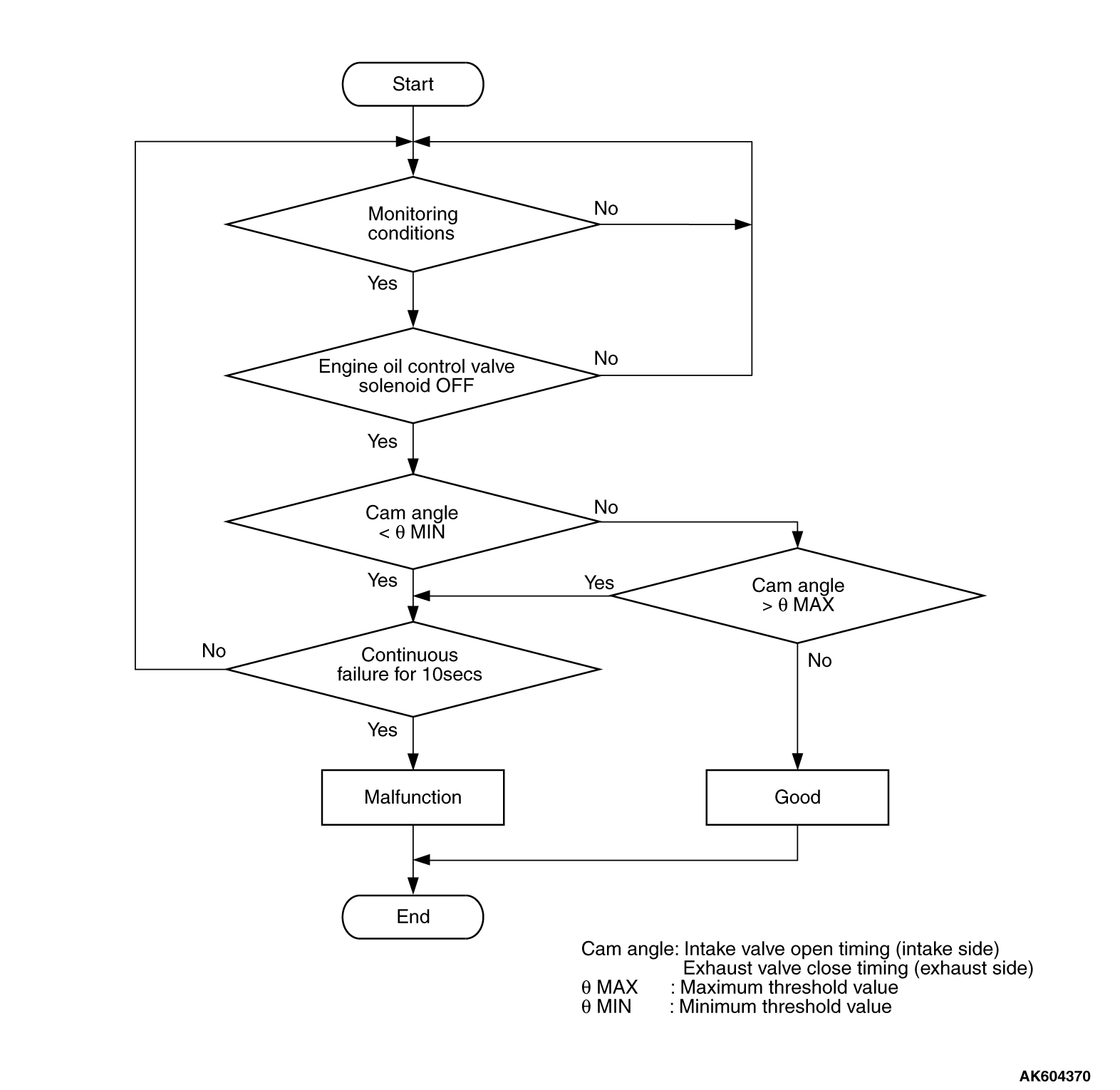
Logic Flow Chart
Check Conditions
- Engine speed is between 594 r/min and 1,500 r/min.
- Engine coolant temperature is between 20°C (68°F) and 88°C (190°F).
- Exhaust engine oil control valve is "OFF".
- 1 second has elapsed after the above mentions have been met.
Judgment Criterion
- The close timing of the exhaust valve is faster than -15 degrees (ATDC) <Except
for California> or -12 degrees (ATDC) <California> for 10 seconds.
or
- The close timing of the exhaust valve is slower than 15 degrees (ATDC) <Except
for California> or 18 degrees (ATDC) <California> for 10 seconds.
OBD-II DRIVE CYCLE PATTERN
Refer to Diagnostic Function -
OBD-II Drive
Cycle -
Pattern 20  .
.
TROUBLESHOOTING HINTS (The most likely causes for this code to be set are:)
- Timing chain in out of place.
- Loose timing chain.
- Exhaust variable valve timing sprocket tooth coming off.
- ECM failed.
|
|
Required Special Tools
- MB991958: Scan tool (M.U.T.-III Sub Assembly)
- MB991824: V.C.I.
- MB991827: USB Cable
- MB991910: Main Harness A
- MB991709: Test Harness
- MB992110: Power Plant ECU Check Harness
|
|
|
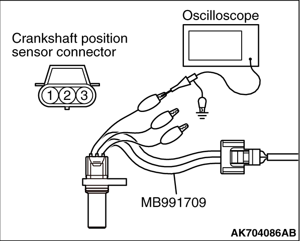
STEP 1. Using the oscilloscope, measure output wave pattern
at crankshaft position sensor and exhaust camshaft position sensor.
|
|
|
(1)Disconnect the crankshaft position sensor connector B-105 and connect the test
harness special tool (MB991709) between the separated connectors.
|
|
(2)Connect the oscilloscope probe to the crankshaft position sensor side connector terminal
No. 3.
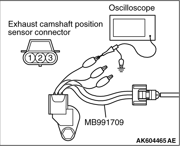
(3)Disconnect the exhaust camshaft position sensor connector B-107, and connect test
harness special tool (MB991709) between the separated connectors.
|
|
(4)Connect the oscilloscope probe to the exhaust camshaft position sensor side connector
terminal No. 3.
| note |
When measuring with the ECM side connector, disconnect all ECM connectors. Connect the
check harness special tool (MB992110) between the separated connectors. Then connect the oscilloscope
probe to the check harness connector terminal No. 8 (crankshaft position sensor) and terminal
No. 7 (exhaust camshaft position sensor).
|
(5)Start the engine and run at idle.
|
|
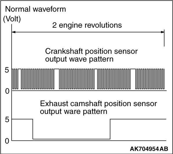
(6)Check the waveform.
- The waveform should show a pattern similar to the illustration.
(7)Turn the ignition switch to the "LOCK" (OFF) position.
Q.
Is the waveform normal?
 Go to Step 2. Go to Step 2.
 Go to Step 3. Go to Step 3.
|
|
|
STEP 2. Check the trouble symptoms.
|
|
|
(1)Carry out a test drive with the drive cycle pattern. Refer to Diagnostic Function -
OBD-II
Drive Cycle -
Pattern 20 .
|
|
|
(2)Check the diagnostic trouble code (DTC).
|
|
|
Replace the ECM. When the ECM is replaced, register the ID code. Refer to GROUP
42B, Diagnosis -
ID Code Registration Judgment Table <Vehicles with KOS> or
GROUP 42C, Diagnosis -
ID Codes Registration Judgment Table <Vehicles with WCM> .
Then go to Step 4.
|
|
|
|
|
|
It can be assumed that this malfunction is intermittent. Refer to GROUP 00, How
to Use Troubleshooting/ Inspection Service Points -
How to Cope with Intermittent Malfunctions .
|
|
|
|
|
|
STEP 3. Check timing mark on the timing chain.
|
|
|
Q.
Is timing chain in out of place?
|
|
|
Repair it. Then go to Step 4.
|
|
|
|
|
|
Check the following items, and repair or replace
the defective items.
- Check the timing chain loose.
- Check the exhaust variable valve timing sprocket tooth coming off.
Then go to Step 4.
|
|
|
|
|
|
STEP 4. Test the OBD-II drive cycle.
|
|
|
(1)Carry out a test drive with the drive cycle pattern. Refer to Diagnostic Function -
OBD-II
Drive Cycle -
Pattern 20 .
|
|
|
(2)Check the diagnostic trouble code (DTC).
|
|
|
Retry the troubleshooting.
|
|
|
|
|
|
The inspection is complete.
|
|
|
|
)
)
)
)