![[Previous]](../../../buttons/fprev.png)
![[Next]](../../../buttons/fnext.png)
DTC P0014: Exhaust
Variable Valve Timing System Target Error
TECHNICAL DESCRIPTION
- The ECM checks the variable valve timing system for malfunction.
DESCRIPTIONS OF MONITOR METHODS
The difference between the actual exhaust valve closing
timing and the exhaust valve target closing timing is over the specified value.
MONITOR EXECUTION
MONITOR EXECUTION CONDITIONS (Other monitor and Sensor)
Other Monitor (There is no temporary DTC stored in memory
for the item monitored below)
Sensor (The sensor below is determined to be normal)
- Camshaft position sensor
- Crankshaft position sensor
- Engine coolant temperature sensor
- Throttle position sensor
- Engine oil control valve
DTC SET CONDITIONS
Logic Flow Chart
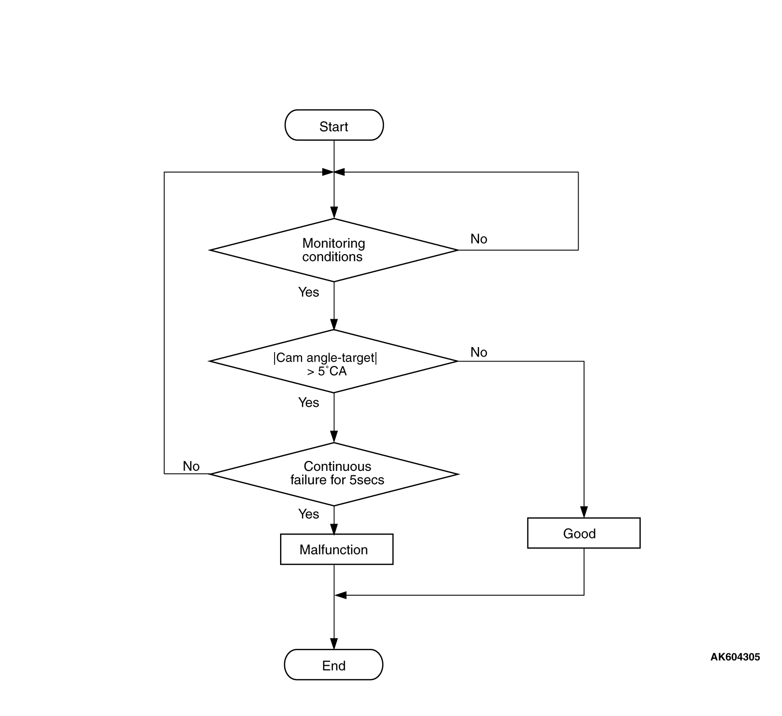
Check Conditions
- More than 20 seconds have passed since the engine starting sequence was completed.
- Engine speed is 1,188 r/min or more.
- Engine coolant temperature is higher than 76°C (169°F).
Judgment Criterion
- The difference between the actual exhaust valve closing timing and the exhaust valve
target closing timing is more than 5 degrees for 5 seconds.
OBD-II DRIVE CYCLE PATTERN
Refer to Diagnostic Function - OBD-II Drive Cycle - Pattern
20  .
.
TROUBLESHOOTING HINTS (The most likely causes for this code to be set are:)
- Exhaust engine oil control valve failed.
- Oil passage of variable valve timing control system clogged.
- Exhaust variable valve timing sprocket operation mechanism stuck.
- ECM failed.
|
|
Required Special Tools
- MB991958: Scan tool (M.U.T.-III Sub Assembly)
- MB991824: V.C.I.
- MB991827: USB Cable
- MB991910: Main Harness A
|
|
|
STEP 1. Using scan tool MB991958, read the diagnostic trouble
code (DTC).
|

|
| caution |
To prevent damage to scan tool MB991958, always turn the ignition switch to the "LOCK"
(OFF) position before connecting or disconnecting scan tool MB991958.
|
(1)Connect scan tool MB991958 to the data link connector.
(2)Turn the ignition switch to the "ON" position.
(3)Set scan tool MB991958, read the DTC.
(4)Turn the ignition switch to the "LOCK" (OFF) position.
Q.
Is the diagnostic trouble code other than P0014 set?
 Refer to, Diagnostic Trouble Code Chart . Refer to, Diagnostic Trouble Code Chart .
 Go to Step 2. Go to Step 2.
|
|
|
STEP 2. Check exhaust engine oil control valve itself.
|
|
|
- Check exhaust engine oil control valve itself (Refer to Engine Oil Control
Valve Check ).
|
|
|
Q.
Is the check result normal?
|
|
|
Go to Step 3.
|
|
|
|
|
|
Replace exhaust engine oil control valve. Then go to Step 6.
|
|
|
|
|
|
STEP 3. Check oil passage of exhaust variable valve timing control
system for being clogged.
|
|
|
Q.
Is the check result normal?
|
|
|
Go to Step 4.
|
|
|
|
|
|
Repair it. Then go to Step 6.
|
|
|
|
|
|
STEP 4. Check exhaust variable valve timing sprocket operation mechanism
for being stuck.
|
|
|
Q.
Is the check result normal?
|
|
|
Go to Step 5.
|
|
|
|
|
|
Repair it. Then go to Step 6.
|
|
|
|
|
|
STEP 5. Check the trouble symptoms.
|
|
|
(1)Carry out test drive with the drive cycle pattern. Refer to Diagnostic Function - OBD-II
Drive Cycle - Pattern 20 .
|
|
|
(2)Check the diagnostic trouble code (DTC).
|
|
|
Replace the ECM. When the ECM is replaced, register the ID code. Refer to GROUP
42B, ID Code Registration Necessity Judgment Table <Vehicles with KOS> or
GROUP 42C, ID Codes Registration Judgment Table <Vehicles with WCM> .
Then go to Step 6.
|
|
|
|
|
|
It can be assumed that this malfunction is intermittent. Refer to GROUP 00, How
to Use Troubleshooting/Inspection Service Points - How to Cope with Intermittent Malfunctions .
|
|
|
|
|
|
STEP 6. Test the OBD-II drive cycle.
|
|
|
(1)Carry out a test drive with the drive cycle pattern. Refer to Diagnostic Function - OBD-II
Drive Cycle - Pattern 20 .
|
|
|
(2)Check the diagnostic trouble code (DTC).
|
|
|
Retry the troubleshooting.
|
|
|
|
|
|
The inspection is complete.
|
|
|
|
)
)