![[Previous]](../../../buttons/fprev.png)
![[Next]](../../../buttons/fnext.png)
DTC P1507: Idle
Control System RPM Higher Than Expected at Low Temperature
TECHNICAL DESCRIPTION
- The amount of air taken in during idling is regulated
by the opening and closing of the throttle valve.
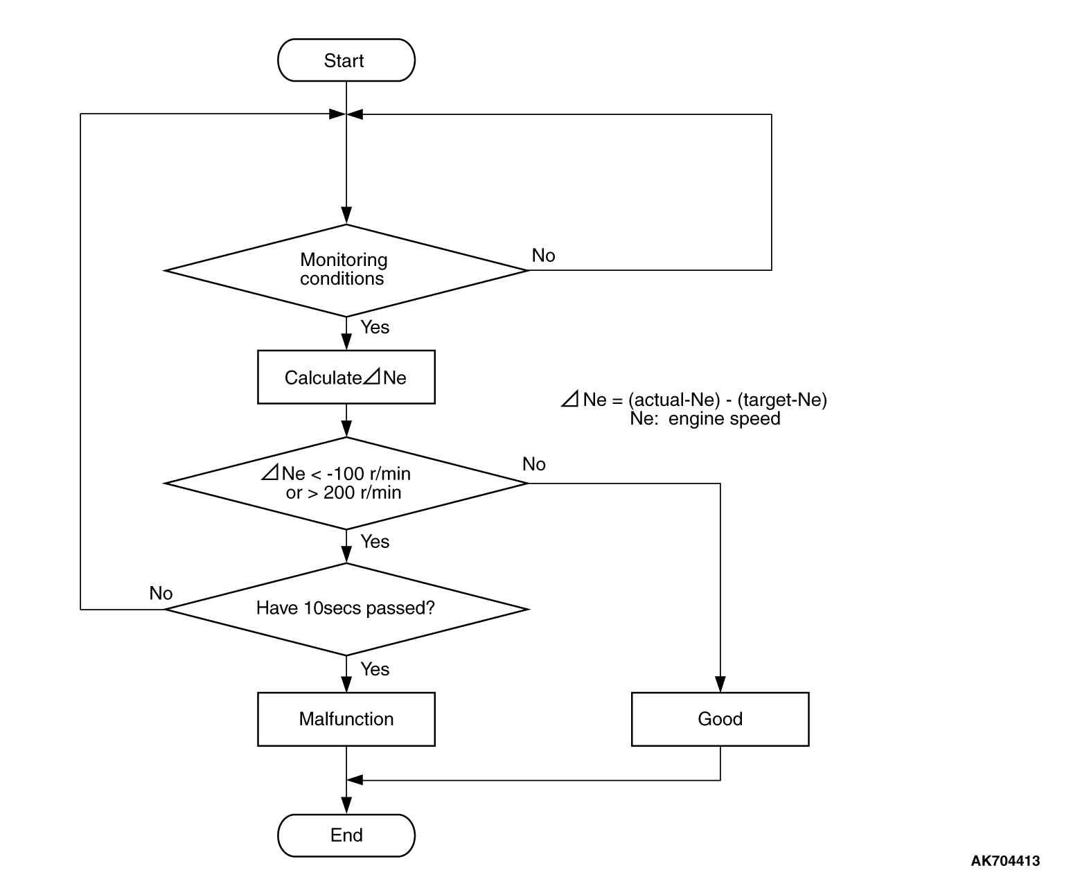
- The ECM checks the difference between the actual engine speed and the target engine
speed.
DESCRIPTIONS OF MONITOR METHODS
Difference between actual and target idle speed is over
the specified value.
MONITOR EXECUTION
MONITOR EXECUTION CONDITIONS (Other monitor and Sensor)
Other Monitor (There is no temporary DTC stored in memory
for the item monitored below)
- Misfire monitor
- Fuel system monitor
- Vehicle speed signal monitor
Sensor (The sensor below is determined to be normal)
- Mass airflow sensor
- Engine coolant temperature sensor
- Intake air temperature sensor
- Barometric pressure sensor
- Throttle position sensor
DTC SET CONDITIONS
Logic Flow Chart
Check Conditions
- Under the closed loop idle speed control.
- Engine coolant temperature is between 7°C (45°F) and 41°C
(106°F).
- Battery positive voltage is more than 10 volts.
- Barometric pressure is more than 76 kPa (22.4 in.Hg).
- Intake air temperature is more than -10°C (14°F).
- More than 3 seconds have passed from the end of the previous monitoring.
- Target air flow rate is 0 g/sec (0 L/sec).
Judgement Criterion
- The actual idle speed is more than the target idle speed by 200 r/min (300
r/min*) or more for 10 seconds.
*: Specs in parentheses are applicable if
the maximum intake air temperature during the previous operation was more than 45°C (113°F).
FAIL-SAFE AND BACKUP FUNCTION
OBD-II DRIVE CYCLE PATTERN
Refer to Diagnostic Function -
OBD-II Drive Cycle -
Pattern
19  .
.
TROUBLESHOOTING HINTS (The most likely causes for this code to be set are:)
- Intake system vacuum leak.
- Throttle body assembly failed.
- ECM failed.
|
|
Required Special Tools
- MB991958: Scan Tool (M.U.T.-III Sub Assembly)
- MB991824: V.C.I.
- MB991827: USB Cable
- MB991910: Main Harness A
|
|
|
STEP 1. Using scan tool MB991958, read the diagnostic trouble
code (DTC).
|

|
| caution |
To prevent damage to scan tool MB991958, always turn the ignition switch to the "LOCK"
(OFF) position before connecting or disconnecting scan tool MB991958.
|
(1)Connect scan tool MB991958 to the data link connector.
(2)Turn the ignition switch to the "ON" position.
(3)After the DTC has been deleted, read the DTC again.
(4)Turn the ignition switch to the "LOCK" (OFF) position.
Q.
Is the diagnostic trouble code other than P1507 set?
 Refer to, Diagnostic Trouble Code Chart . Refer to, Diagnostic Trouble Code Chart .
 Go to Step 2. Go to Step 2.
|
|
|
STEP 2. Check for intake system vacuum leak.
|
|
|
Q.
Are there any abnormalities?
|
|
|
Repair it. Then go to Step 4.
|
|
|
|
|
|
Go to Step 3.
|
|
|
|
|
|
STEP 3. Replace the throttle body assembly.
|
|
|
(1)Replace the throttle body assembly.
|
|
|
(2)Carry out a test drive with the drive cycle pattern. Refer to Diagnostic Function -
OBD-II
Drive Cycle -
Pattern 19 .
|
|
|
(3)Check the diagnostic trouble code (DTC).
|
|
|
Replace the ECM. When the ECM is replaced, register the ID code. Refer to GROUP
42B, Diagnosis -
ID Code Registration Necessity Judgment Table <Vehicles with KOS> or
GROUP 42C, Diagnosis -
ID Codes Registration Judgment Table <Vehicles with WCM> .
Then go to Step 4.
|
|
|
|
|
|
The inspection is complete.
|
|
|
|
|
|
STEP 4. Test the OBD-II drive cycle.
|
|
|
(1)Carry out a test drive with the drive cycle pattern. Refer to Diagnostic Function -
OBD-II
Drive Cycle -
Pattern 19 .
|
|
|
(2)Check the diagnostic trouble code (DTC).
|
|
|
Retry the troubleshooting.
|
|
|
|
|
|
The inspection is complete.
|
|
|
|
)
)