|
|
Required Special Tools:
- MB991958: Scan tool (M.U.T.-III Sub Assembly)
- MB991824: V.C.I.
- MB991827: USB Cable
- MB991910: Main Harness A
|
|
|
Q.
Is the harness connector in good condition?
|
|
|
 Repair or replace it. Refer to GROUP 00E, Harness Connector Inspection Repair or replace it. Refer to GROUP 00E, Harness Connector Inspection  .
Then go to Step 9. .
Then go to Step 9.
|
|
|
|
|
|
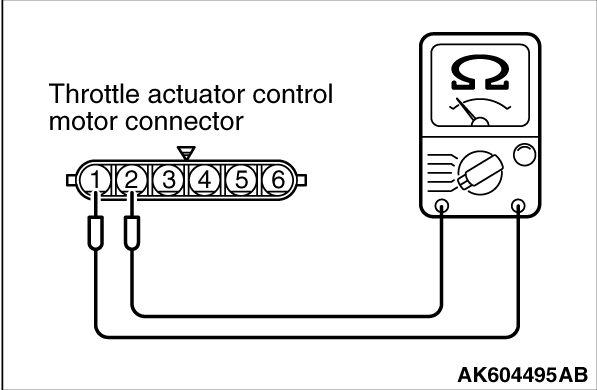
(1)Disconnect the connector B-10.
|
|
(2)Measure the resistance between throttle actuator control motor side connector terminal
No. 1 and No. 2.
Standard value: 0.3 -
80 Ω
[at 20°C (68°F)]
Q.
Is the measured resistance between 0.3 and 80 Ω
[at 20°C
(68°F)]?
 Go to Step 3. Go to Step 3.
Replace the throttle body assembly. Then go to Step 9.
|
|
|
Q.
Is the harness connector in good condition?
|
|
|
Repair or replace it. Refer to GROUP 00E, Harness Connector Inspection .
Then go to Step 9.
|
|
|
|
|
|
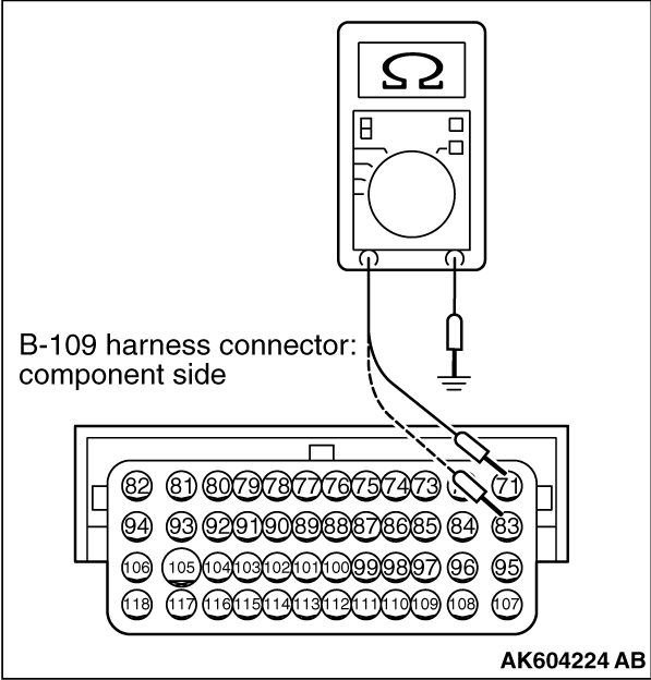
(1)Disconnect the connector B-109 and measure at the harness side.
|
|
(2)Measure the continuity between terminals No. 71, No. 83 and ground.
Q.
Does continuity exist?
Go to Step 5.
Repair harness wire between ECM connector B-109 (terminals No. 71, No. 83) and
ground because of open circuit or harness damage. Then go to Step 9.
|
|
|
Q.
Is the harness connector in good condition?
|
|
|
Repair or replace it. Refer to GROUP 00E, Harness Connector Inspection .
Then go to Step 9.
|
|
|
|
|
|
Q.
Is the harness wire in good condition?
|
|
|
Repair it. Then go to Step 9.
|
|
|
|
|
|
Q.
Is the harness wire in good condition?
|
|
|
Repair it. Then go to Step 9.
|
|
|
|

|
| caution |
To prevent damage to scan tool MB991958, always turn the ignition switch to
the "LOCK" (OFF) position before connecting or disconnecting scan tool MB991958.
|
(1)Connect scan tool MB991958 to the data link connector.
(2)Turn the ignition switch to the "ON" position.
(3)After the DTC has been deleted, read the DTC again.
(4)Turn the ignition switch to the "LOCK" (OFF) position.
Q.
Is DTC P2100 set?
Replace the ECM. When the ECM is replaced, register the ID code. Refer to GROUP
42B, Diagnosis -
ID Code Registration Judgment Table <Vehicles with KOS> or
GROUP 42C, Diagnosis -
ID Codes Registration Judgment Table <Vehicles with WCM> .
Then go to Step 9.
It can be assumed that this malfunction is intermittent. Refer to GROUP 00, How
to Use Troubleshooting/Inspection Service Points -
How to Cope with Intermittent Malfunctions .
|
|
| caution |
To prevent damage to scan tool MB991958, always turn the ignition switch to
the "LOCK" (OFF) position before connecting or disconnecting scan tool MB991958.
|
(1)Connect scan tool MB991958 to the data link connector.
(2)Turn the ignition switch to the "ON" position.
(3)After the DTC has been deleted, read the DTC again.
(4)Turn the ignition switch to the "LOCK" (OFF) position.
Q.
Is DTC P2100 set?
Retry the troubleshooting.
The inspection is complete.
|
![[Previous]](../../../buttons/fprev.png)
![[Next]](../../../buttons/fnext.png)
)
)
)
)
)
)