|
|
Required Special Tools:
- MB991958: Scan tool (M.U.T.-III Sub Assembly)
- MB991824: V.C.I.
- MB991827: USB Cable
- MB991910: Main Harness A
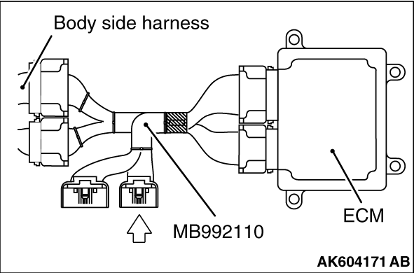
- MB992110: Power Plant ECU Check Harness
|

|
| caution |
To prevent damage to scan tool MB991958, always turn the ignition switch to the "LOCK"
(OFF) position before connecting or disconnecting scan tool MB991958.
|
(1)Connect scan tool MB991958 to the data link connector.
(2)Turn the ignition switch to the "ON" position.
(3)Erase the DTC.
(4)Start the engine and run it at idle.
(5)Read the DTC.
(6)Turn the ignition switch to the "LOCK" (OFF) position.
Q.
Is DTC P1603 set?
 Go to Step 2. Go to Step 2.
 It can be assumed that this malfunction is intermittent. Refer to GROUP 00, How
to Use Troubleshooting/Inspection Service Points -
How to Cope with Intermittent Malfunctions It can be assumed that this malfunction is intermittent. Refer to GROUP 00, How
to Use Troubleshooting/Inspection Service Points -
How to Cope with Intermittent Malfunctions  . .
|
|
|
Q.
Is the harness connector in good condition?
|
|
|
Repair or replace it. Refer to GROUP 00E, Harness Connector Inspection .
Then go to Step 5.
|
|
|
|
|
(1)Disconnect all ECM connectors. Connect the power plant ECU check harness special
tool MB992110 between the separated connectors.
|
|
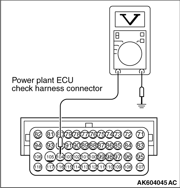
(2)Measure the voltage between terminal No. 104 and ground.
- Voltage should be battery positive voltage.
Q.
Is battery positive voltage (approximately 12 volts) present?
Replace the ECM. When the ECM is replaced, register the ID code. Refer to GROUP
42B, Diagnosis -
ID Code Registration Judgment Table <Vehicles with KOS> or
GROUP 42C, Diagnosis -
ID Codes Registration Judgment Table <Vehicles with WCM> .
Then go to Step 5.
Go to Step 4.
|
|
|
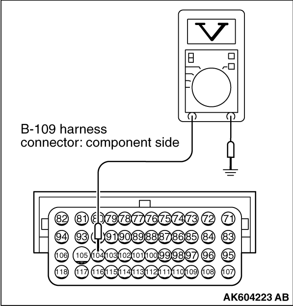
(1)Disconnect the ECM connector B-109 and measure at the harness side.
|
|
(2)Measure the voltage between terminal No. 104 and ground.
- Voltage should be battery positive voltage.
Q.
Is battery positive voltage (approximately 12 volts) present?
Repair harness wire between battery and ECM connector B-109 (terminal No. 104)
because of harness damage. Then go to Step 5.
Repair harness wire between battery and ECM connector B-109 (terminal No. 104)
because of open circuit or short circuit to ground. Then go to Step 5.
|
|
|
(1)Turn the ignition switch to the "ON" position.
|
|
|
(3)Turn the ignition switch to the "LOCK" (OFF) position.
|
|
|
Retry the troubleshooting.
|
|
|
|
|
|
The inspection is complete.
|
|
|
|
![[Previous]](../../../buttons/fprev.png)
![[Next]](../../../buttons/fnext.png)
)
)
)
)
)
)
)