![[Previous]](../../../buttons/fprev.png)
![[Next]](../../../buttons/fnext.png)
DTC P0500: Vehicle
Speed Sensor Malfunction <M/T>
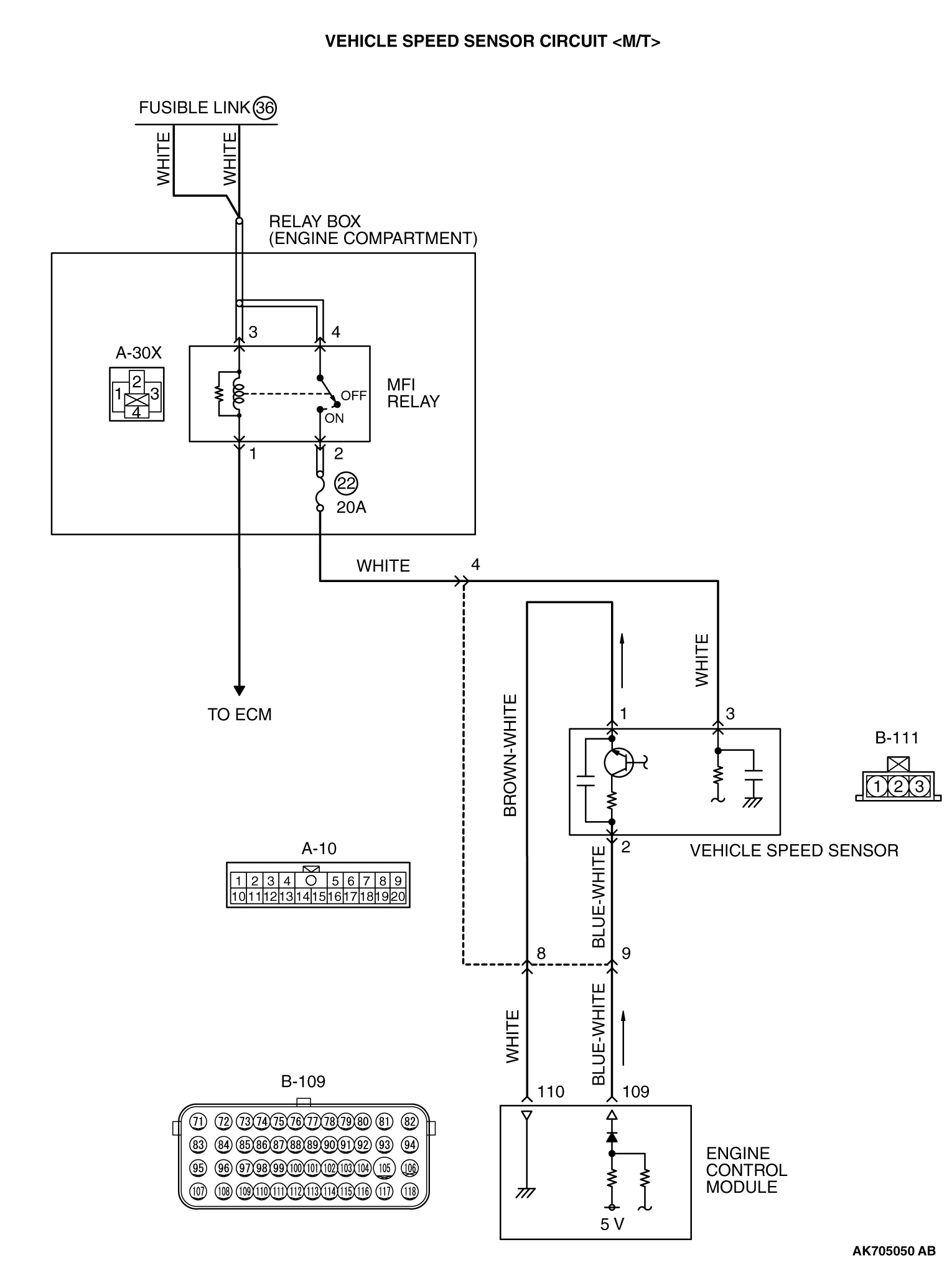
CIRCUIT OPERATION
- A 5-volt voltage is applied to the vehicle speed sensor
output terminal (terminal No. 2) from the ECM (terminal No. 109). The vehicle speed sensor generates
a pulse signal when the output terminal is opened and grounded.
TECHNICAL DESCRIPTION
- The vehicle speed sensor converts the vehicle speed into
pulse signals and inputs them to the ECM.
- The vehicle speed sensor outputs a pulse signal while the vehicle is driven.
- The ECM checks whether the pulse signal is output.
DESCRIPTIONS OF MONITOR METHODS
- If the vehicle speed sensor output does not change while
the vehicle is being driven in the medium- to high-speed range, a malfunction is determined
to have occurred.
MONITOR EXECUTION
MONITOR EXECUTION CONDITIONS (Other monitor and Sensor)
Other Monitor (There is no temporary DTC stored in memory
for the item monitored below)
Sensor (The sensor below is determined to be normal)
DTC SET CONDITIONS (Entry Conditions and Malfunction Thresholds)
Logic Flow Chart
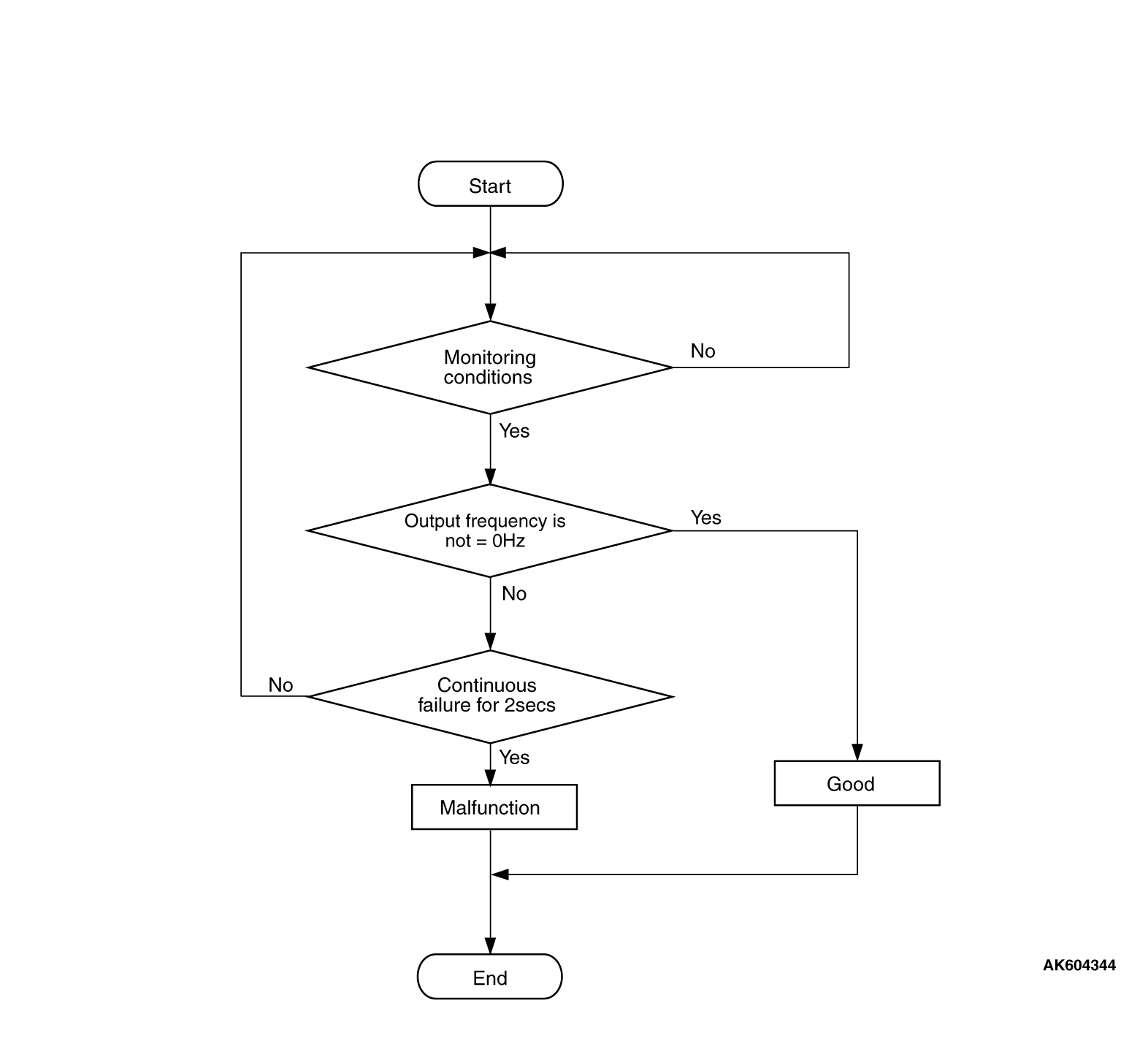
Check Conditions
- 2 seconds or more have passed since the engine starting sequence was completed.
- Engine speed is between 2,000 and 4,000 r/min.
- Volumetric efficiency is between 40 and 65 percent.
Judgement Criterion
- Vehicle speed sensor output voltage has not changed (no pulse signal is input) for
2 seconds.
OBD-II DRIVE CYCLE PATTERN
None
TROUBLESHOOTING HINTS (The most likely causes for this code to be set are: )
- Vehicle speed sensor failed.
- Open or shorted vehicle speed sensor circuit, or harness damage, or connector damage.
- ECM failed.
|
|
Required Special Tools:
- MB991958: Scan Tool (M.U.T.-III Sub Assembly)
- MB991824: V.C.I.
- MB991827: USB Cable
- MB991910: Main Harness A
|
|
|
STEP 1. Using scan tool MB991958, check data list item
4: Vehicle Speed Sensor.
|

|
| caution |
To prevent damage to scan tool MB991958, always turn the ignition switch to the "LOCK"
(OFF) position before connecting or disconnecting scan tool MB991958.
|
(1)Connect scan tool MB991958 to the data link connector.
(2)Start the engine.
(3)Set scan tool MB991958 to the data reading mode for item 4, Vehicle Speed Sensor.
- Check that the speedometer and M.U.T.-III display speed
match when traveling at a vehicle speed of 40 km/h (25 mph).
(4)Turn the ignition switch to the "LOCK" (OFF) position.
Q.
Is the sensor operating properly?
 It can be assumed that this malfunction is intermittent. Refer to GROUP 00, How
to Use Troubleshooting/Inspection Service Points -
How to Cope with Intermittent
Malfunctions It can be assumed that this malfunction is intermittent. Refer to GROUP 00, How
to Use Troubleshooting/Inspection Service Points -
How to Cope with Intermittent
Malfunctions  . .
 Go to Step 2. Go to Step 2.
|
|
|
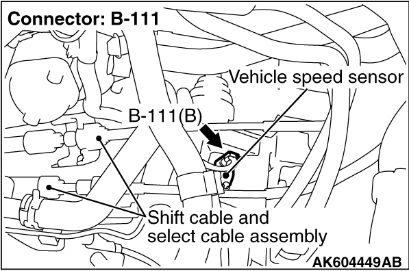
STEP 2. Check connector B-111 at vehicle speed sensor for damage.
|
|
|
Q.
Is the connector in good condition?
|
|
|
Go to Step 3.
|
|
|
|
|
|
Repair or replace it. Refer to GROUP 00E, Harness Connector Inspection .
Then go to Step 17.
|
|
|
|
|
|
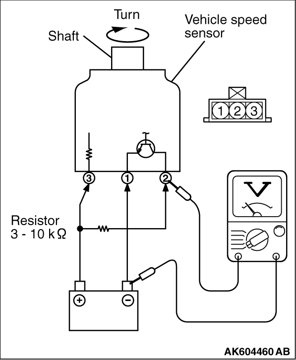
STEP 3. Check the vehicle speed sensor.
|
|
1.Remove the vehicle speed sensor and connect a 3 -
10 kΩ
resistor as
shown in the illustration.
2.Turn the shaft of the vehicle speed sensor and check that there is voltage between
terminals 2 -
3. (1 turn =
4 pulses)
Standard value: 0 or Battery Voltage (1 turn =
4pulses)
Q.
Is the vehicle speed sensor normal?
Go to Step 4.
Replace the vehicle speed sensor. Then go to Step 17.
|
|
|
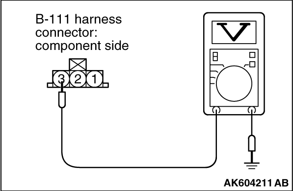
STEP 4. Measure the power supply voltage at vehicle speed sensor connector
B-111.
|
|
|
(1)Disconnect the connector B-111 and measure at the harness side.
|
|
|
(2)Turn the ignition switch to the "ON" position.
|
|
(3)Measure the voltage between terminal No. 3 and ground.
- Voltage should be battery positive voltage.
(4)Turn the ignition switch to the "LOCK" (OFF) position.
Q.
Is battery positive voltage (approximately 12 volts) present?
Go to Step 6.
Go to Step 5.
|
|
|
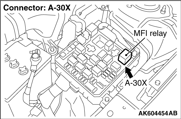
STEP 5. Check harness connector A-30X at MFI relay for damage.
|
|
|
Q.
Is the harness connector in good condition?
|
|
|
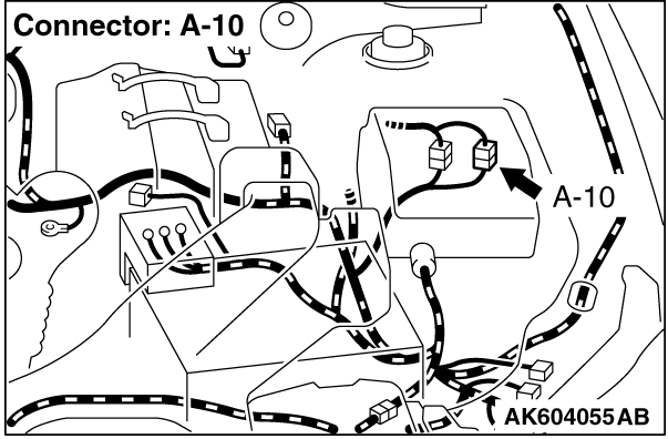
Check harness connector A-10 at intermediate connector for damage, and repair
or replace as required. Refer to GROUP 00E, Harness Connector Inspection .
If intermediate connector is in good condition, repair harness wire between MFI relay connector
A-30X (terminal No. 2) and vehicle speed sensor connector B-111 (terminal No. 3) because of open
circuit or short circuit to ground. Then go to Step 17.
|
|
|
|
|
|
Repair or replace it. Refer to GROUP 00E, Harness Connector Inspection .
Then go to Step 17.
|
|
|
|
|
|
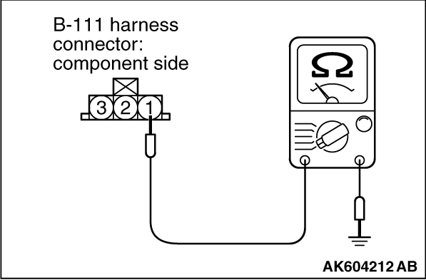
STEP 6. Check the continuity at vehicle speed sensor harness side
connector B-111.
|
|
|
(1)Disconnect the connector B-111 and measure at the harness side.
|
|
(2)Check for the continuity between terminal No. 1 and ground.
Q.
Does the continuity exist?
Go to Step 10.
Go to Step 7.
|
|
|
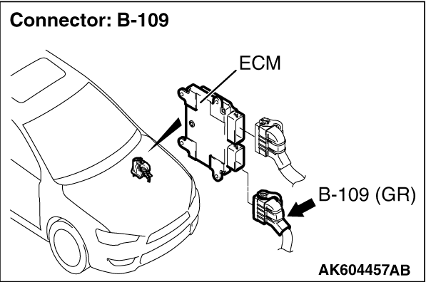
STEP 7. Check connector B-109 at ECM for damage.
|
|
|
Q.
Is the connector in good condition?
|
|
|
Go to Step 8.
|
|
|
|
|
|
Repair or replace it. Refer to GROUP 00E, Harness Connector Inspection .
Then go to Step 17.
|
|
|
|
|
|
STEP 8. Check for open circuit and harness damage between vehicle
speed sensor connector B-111 (terminal No. 1) and ECM connector B-109 (terminal No. 110).
|
|
|
| note |
Check harness connector after checking intermediate connector A-10. If intermediate connector
is damaged, repair or replace it. Refer to GROUP 00E, Harness Connector Inspection .
Then go to Step 17.
|
|
|
|
Q.
Is the harness wire in good condition?
|
|
|
Go to Step 9.
|
|
|
|
|
|
Repair it. Then go to Step 17.
|
|
|
|
|
|
STEP 9. Using scan tool MB991958, check data list item 4: Vehicle
Speed Sensor.
|
|
|
(2)Set scan tool MB991958 to the data reading mode for item 4, Vehicle Speed Sensor.
- Check that the speedometer and M.U.T.-III display speed
match when traveling at a vehicle speed of 40 km/h (25 mph).
|
|
|
(3)Turn the ignition switch to the "LOCK" (OFF) position.
|
|
|
Q.
Is the sensor operating properly?
|
|
|
It can be assumed that this malfunction is intermittent. Refer to GROUP 00, How
to Use Troubleshooting/Inspection Service Points -
How to Cope with Intermittent
Malfunctions .
|
|
|
|
|
|
Replace the ECM. When the ECM is replaced, register the ID code. Refer to GROUP
42B, Diagnosis -
ID Code Registration Judgment Table <Vehicles with KOS> or
GROUP 42C, Diagnosis -
ID Codes Registration Judgment Table <Vehicles with WCM> .
Then go to Step 17.
|
|
|
|
|
|
STEP 10. Measure the sensor supply voltage at vehicle speed sensor
harness side connector B-111.
|
|
|
(1)Disconnect the vehicle speed sensor connector B-111 and measure at the harness
side.
|
|
|
(2)Turn the ignition switch to the "ON" position.
|
|
|
(3)Measure the voltage between terminal No. 2 and ground.
- Voltage should be between 4.9 and 5.1 volts.
|
|
|
(4)Turn the ignition switch to the "LOCK" (OFF) position.
|
|
|
Q.
Is the measured voltage between 4.9 and 5.1 volts?
|
|
|
Go to Step 14.
|
|
|
|
|
|
Go to Step 11.
|
|
|
|
|
|
STEP 11. Check connector B-109 at ECM for damage.
|
|
|
Q.
Is the connector in good condition?
|
|
|
Go to Step 12.
|
|
|
|
|
|
Repair or replace it. Refer to GROUP 00E, Harness Connector Inspection .
Then go to Step 17.
|
|
|
|
|
|
STEP 12. Check for open circuit and short circuit to ground between
vehicle speed sensor connector B-111 (terminal No. 2) and ECM connector B-109 (terminal No. 109).
|
|
|
| note |
Check harness connector after checking intermediate connector A-10. If intermediate connector
is damaged, repair or replace it. Refer to GROUP 00E, Harness Connector Inspection .
Then go to Step 17.
|
|
|
|
Q.
Is the harness wire in good condition?
|
|
|
Go to Step 13.
|
|
|
|
|
|
Repair it. Then go to Step 17.
|
|
|
|
|
|
STEP 13. Using scan tool MB991958, check data list item 4: Vehicle
Speed Sensor.
|
|
|
(2)Set scan tool MB991958 to the data reading mode for item 4, Vehicle Speed Sensor.
- Check that the speedometer and M.U.T.-III display speed
match when traveling at a vehicle speed of 40 km/h (25 mph).
|
|
|
(3)Turn the ignition switch to the "LOCK" (OFF) position.
|
|
|
Q.
Is the sensor operating properly?
|
|
|
It can be assumed that this malfunction is intermittent. Refer to GROUP 00, How
to Use Troubleshooting/Inspection Service Points -
How to Cope with Intermittent
Malfunctions .
|
|
|
|
|
|
Replace the ECM. When the ECM is replaced, register the ID code. Refer to GROUP
42B, Diagnosis -
ID Code Registration Judgment Table <Vehicles with KOS> or
GROUP 42C, Diagnosis -
ID Codes Registration Judgment Table <Vehicles with WCM> .
Then go to Step 17.
|
|
|
|
|
|
STEP 14. Check connectors B-109 at ECM for damage.
|
|
|
Q.
Is the connector in good condition?
|
|
|
Go to Step 15.
|
|
|
|
|
|
Repair or replace it. Refer to GROUP 00E, Harness Connector Inspection .
Then go to Step 17.
|
|
|
|
|
|
STEP 15. Check for harness damage between MFI relay connector A-30X
(terminal No. 2) and vehicle speed sensor connector B-109 (terminal No. 3).
|
|
|
| note |
Check harness connector after checking intermediate connector A-10. If intermediate connector
is damaged, repair or replace it. Refer to GROUP 00E, Harness Connector Inspection .
Then go to Step 17.
|
|
|
|
Q.
Is the harness wire in good condition?
|
|
|
Go to Step 16.
|
|
|
|
|
|
Repair it. Then go to Step 17.
|
|
|
|
|
|
STEP 16. Check for harness damage between vehicle speed sensor connector
B-111 (terminal No. 2) and ECM connector B-109 (terminal No. 109).
|
|
|
| note |
Check harness after checking intermediate connector A-10. If intermediate connector is
damaged, repair or replace it. Refer to GROUP 00E, Harness Connector Inspection . Then
go to Step 17.
|
|
|
|
Q.
Is the harness wire in good condition?
|
|
|
Go to Step 17.
|
|
|
|
|
|
Repair it. Then go to Step 17.
|
|
|
|
|
|
STEP 17. Using scan tool MB991958, check data list item 4: Vehicle
Speed Sensor.
|
|
|
(2)Set scan tool MB991958 to the data reading mode for item 4, Vehicle Speed Sensor.
- Check that the speedometer and M.U.T.-III display speed
match when traveling at a vehicle speed of 40 km/h (25 mph).
|
|
|
(3)Turn the ignition switch to the "LOCK" (OFF) position.
|
|
|
Q.
Is the sensor operating properly?
|
|
|
The inspection is complete.
|
|
|
|
|
|
Retry the troubleshooting.
|
|
|
|
)
)
)
)
)
)
)
)
)
)