![[Previous]](../../../buttons/fprev.png)
![[Next]](../../../buttons/fnext.png)
DTC P0181: Fuel
Tank Temperature Sensor Circuit Range/Performance
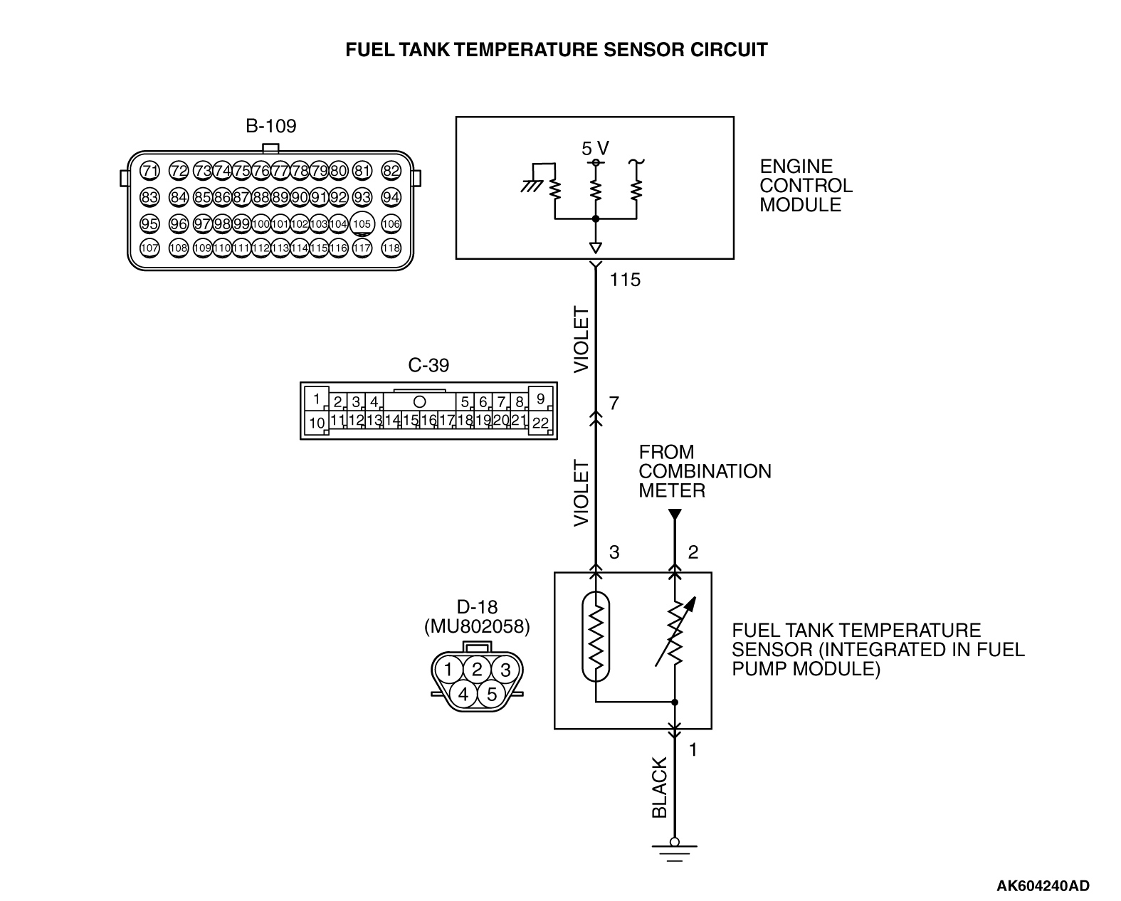
CIRCUIT OPERATION
- 5-volt voltage is applied to the fuel tank temperature
sensor output terminal (terminal No. 3) from the ECM (terminal No. 115) via the resistor in
the ECM.
- The fuel tank temperature sensor output voltage increases when the resistance increases
and decreases when the resistance decreases. The ground terminal (terminal No. 1) is grounded
to the vehicle body.
TECHNICAL DESCRIPTION
- The fuel tank temperature sensor converts the fuel tank
temperature to a voltage.
- The ECM detects the fuel tank temperature with this output voltage.
DESCRIPTIONS OF MONITOR METHODS
Fuel tank temperature at engine start is higher than
engine coolant temperature at engine start by specified value when engine is cold start condition.
MONITOR EXECUTION
MONITOR EXECUTION CONDITIONS (Other monitor and Sensor)
Other Monitor (There is no temporary DTC stored in memory
for the item monitored below)
Sensor (The sensor below is determined to be normal)
- Engine coolant temperature sensor
- Intake air temperature sensor
DTC SET CONDITIONS
Logic Flow Chart

Check Conditions
- The engine coolant temperature - intake air temperature is 5°C (9°F)
or less when the engine is started.
- The engine coolant temperature is between
-10°C (14°F) and 36°C (97°F) when the engine
is started.
- The engine coolant temperature is higher than 60°C (140°F).
- Maximum vehicle speed is higher than 30 km/h (19 mph) after the engine starting
sequence has been completed.
Judgement Criterion
- The fuel tank temperature - engine coolant temperature is 15°C
(27°F) or more when the engine is started.
OBD-II DRIVE CYCLE PATTERN
Refer to Diagnostic Function - OBD-II Drive
Cycle - Pattern 14  .
.
TROUBLESHOOTING HINTS (The most likely causes for this code to be set are:)
- Fuel tank temperature sensor failed.
- Open or shorted fuel tank temperature sensor circuit, harness damage, or connector
damage.
- ECM failed.
| note |
A diagnostic trouble code (DTC) could be output if the engine and the radiator have been
flushed repeatedly when the engine coolant temperature was high (or the fuel tank temperature
was high). Because this is not a failure, the DTC must be erased.
Make sure to test drive the vehicle in accordance with the OBD-II drive cycle pattern
in order to verify that a DTC will not be output.
|
|
|
Required Special Tools:
- MB991958: Scan Tool (M.U.T.-III Sub Assembly)
- MB991824: V.C.I.
- MB991827: USB Cable
- MB991910: Main Harness A
- MB992110: Power Plant ECU Check Harness
|
|
|
STEP 1. Using scan tool MB991958, check data list item
53: Fuel Tank Temperature Sensor.
|

|
| caution |
To prevent damage to scan tool MB991958, always turn the ignition switch to the "LOCK"
(OFF) position before connecting or disconnecting scan tool MB991958.
|
(1)Connect scan tool MB991958 to the data link connector.
(2)Turn the ignition switch to the "ON" position.
(3)Set scan tool MB991958 to the data reading mode for item 53, Fuel Tank Temperature
Sensor.
- Approximately the same as the ambient air temperature
when the engine is cooled.
(4)Turn the ignition switch to the "LOCK" (OFF) position.
Q.
Is the sensor operating properly?
 It can be assumed that this malfunction is intermittent. Refer to GROUP 00, How
to Use Troubleshooting/Inspection Service Points - How to Cope with Intermittent
Malfunctions . It can be assumed that this malfunction is intermittent. Refer to GROUP 00, How
to Use Troubleshooting/Inspection Service Points - How to Cope with Intermittent
Malfunctions .
 Go to Step 2. Go to Step 2.
|
|
|
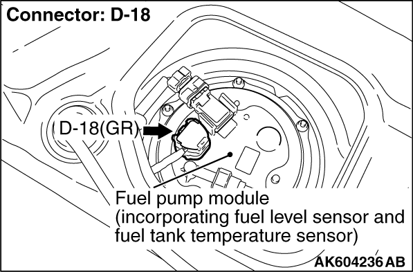
STEP 2. Check harness connector D-18 at the fuel tank temperature
sensor for damage.
|
|
|
Q.
Is the harness connector in good condition?
|
|
|
Go to Step 3.
|
|
|
|
|
|
Repair or replace it. Refer to GROUP 00E, Harness Connector Inspection .
Then go to Step 11.
|
|
|
|
|
|
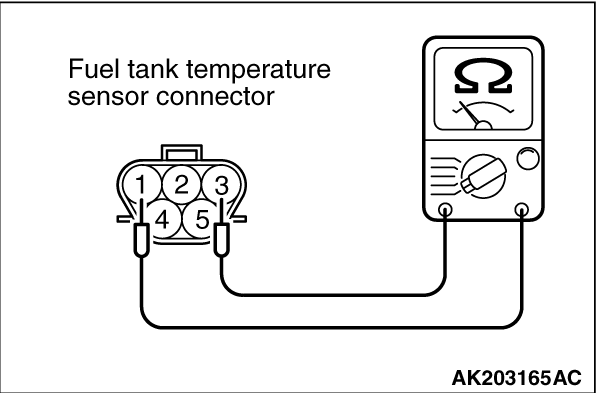
STEP 3. Check the fuel tank temperature sensor.
|
|
|
(1)Disconnect the fuel tank temperature sensor connector D-18.
|
|
(2)Measure the resistance between terminal No. 1 and No. 3 of the fuel tank temperature sensor.
Standard value: 0.5 - 12.0 kΩ
Q.
Is the measured resistance between 0.5 and 12.0 kΩ?
Go to Step 4.
Replace the fuel tank temperature sensor. Then go to Step 11.
|
|
|
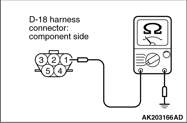
STEP 4. Check the continuity at fuel tank temperature sensor harness
side connector D-18.
|
|
|
(1)Disconnect the connector D-18 and measure at the harness side.
|
|
(2)Check for the continuity between terminal No. 1 and ground.
Q.
Does continuity exist?
Go to Step 5.
Repair harness wire between fuel tank temperature sensor connector D-18 (terminal
No. 1) and ground because of open circuit or harness damage. Then go to Step 11.
|
|
|
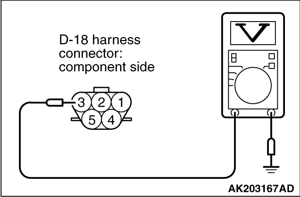
STEP 5. Measure the sensor supply voltage at fuel tank temperature
sensor harness side connector D-18.
|
|
|
(1)Disconnect the connector D-18 and measure at the harness side.
|
|
|
(2)Turn the ignition switch to the "ON" position.
|
|
(3)Measure the voltage between terminal No. 3 and ground.
- Voltage should be between 4.5 and 4.9 volts
(4)Turn the ignition switch to the "LOCK" (OFF) position.
Q.
Is the measured voltage between 4.5 and 4.9 volts?
Go to Step 9.
Go to Step 6.
|
|
|
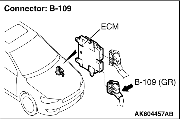
STEP 6. Check harness connector B-109 at ECM for damage.
|
|
|
Q.
Is the harness connector in good condition?
|
|
|
Go to Step 7.
|
|
|
|
|
|
Repair or replace it. Refer to GROUP 00E, Harness Connector Inspection .
Then go to Step 11.
|
|
|
|
|
|
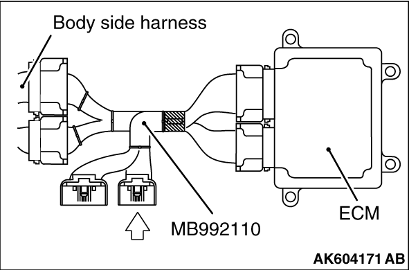
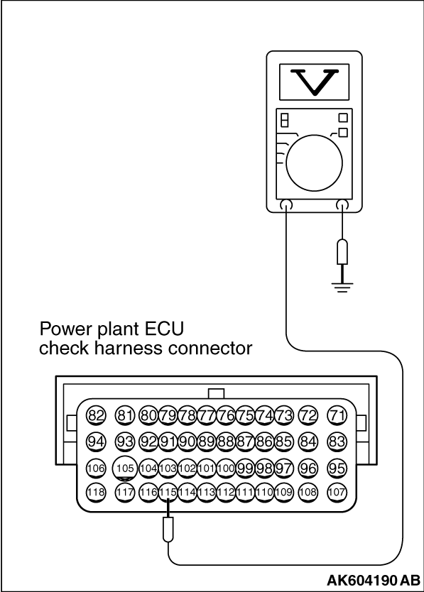
STEP 7. Measure the sensor supply voltage at ECM connector B-109 by
using power plant ECU check harness special tool MB992110.
|
|
(1)Disconnect all ECM connectors. Connect the power plant ECU check harness special
tool MB992110 between the separated connectors.
(2)Turn the ignition switch to the "ON" position.
|
|
(3)Measure the voltage between terminal No. 115 and ground.
- When fuel tank temperature is 0°C (32°F),
voltage should be between 2.7 and 3.1 volts.
- When fuel tank temperature is 20°C (68°F), voltage should be between
2.1 and 2.5 volts.
- When fuel tank temperature is 40°C (104°F), voltage should be
between 1.6 and 2.0 volts.
- When fuel tank temperature is 80°C (176°F), voltage should be
between 0.8 and 1.2 volts.
(4)Turn the ignition switch to the "LOCK" (OFF) position.
Q.
Is the measured voltage normal?
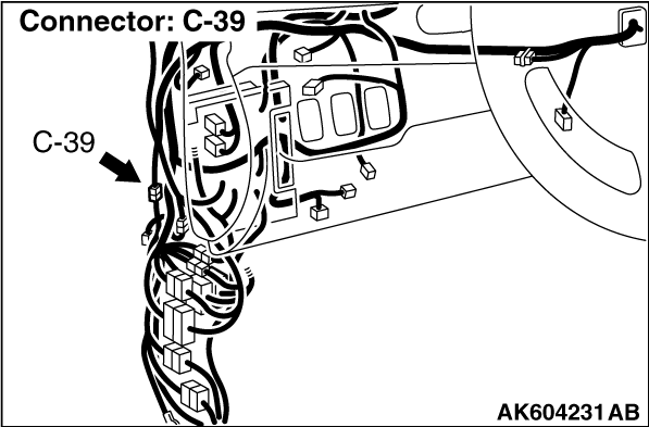
Check harness connector C-39 at intermediate connector for damage, and repair
or replace as required. Refer to GROUP 00E, Harness Connector Inspection .
If intermediate connector is in good condition, repair harness wire between fuel tank temperature
sensor connector D-18 (terminal No. 3) and ECM connector B-109 (terminal No. 115) because of
open circuit. Then go to Step 11.
Go to Step 8.
|
|
|
STEP 8. Check for short circuit to ground between fuel tank temperature
sensor connector D-18 (terminal No. 3) and ECM connector B-109 (terminal No. 115).
|
|
|
| note |
Check harness after checking intermediate connector C-39. If intermediate connector is damaged,
repair or replace it. Refer to GROUP 00E, Harness Connector Inspection .
Then go to Step 11.
|
|
|
|
Q.
Is the harness wire in good condition?
|
|
|
Replace the ECM. When the ECM is replaced, register the ID code. Refer to GROUP
42B, Diagnosis - ID Code Registration Judgment Table <Vehicles with KOS> or
GROUP 42C, Diagnosis - ID Codes Registration Judgment Table <Vehicles with WCM> .
Then go to Step 11.
|
|
|
|
|
|
Repair it. Then go to Step 11.
|
|
|
|
|
|
STEP 9. Check harness connector B-109 at ECM for damage.
|
|
|
Q.
Is the harness connector in good condition?
|
|
|
Go to Step 10.
|
|
|
|
|
|
Repair or replace it. Refer to GROUP 00E, Harness Connector Inspection .
Then go to Step 11.
|
|
|
|
|
|
STEP 10. Check for harness damage between fuel tank temperature sensor
connector D-18 (terminal No. 3) and ECM connector B-109 (terminal No. 115).
|
|
|
| note |
Check harness after checking intermediate connector C-39. If intermediate connector is damaged,
repair or replace it. Refer to GROUP 00E, Harness Connector Inspection .
Then go to Step 11.
|
|
|
|
Q.
Is the harness wire in good condition?
|
|
|
Replace the ECM. When the ECM is replaced, register the ID code. Refer to GROUP
42B, Diagnosis - ID Code Registration Judgment Table <Vehicles with KOS> or
GROUP 42C, Diagnosis - ID Codes Registration Judgment Table <Vehicles with WCM> .
Then go to Step 11.
|
|
|
|
|
|
Repair it. Then go to Step 11.
|
|
|
|
|
|
STEP 11. Test the OBD-II drive cycle.
|
|
|
(1)Carry out a test drive with the drive cycle pattern. Refer to Diagnostic Function - OBD-II
Drive Cycle - Pattern 14 .
|
|
|
(2)Check the diagnostic trouble code (DTC).
|
|
|
Retry the troubleshooting.
|
|
|
|
|
|
The inspection is complete.
|
|
|
|
)
)
)
)
)
)
)
)
)
)
)