![[Previous]](../../../buttons/fprev.png)
![[Next]](../../../buttons/fnext.png)
DTC P0172: System
too Rich
Fuel Trim Circuit
- Refer to DTC P0201 -
Injector Circuit-Cylinder 1
 ,
DTC P0202 -
Injector Circuit-Cylinder 2 , DTC
P0203 -
Injector Circuit-Cylinder 3 , DTC P0204 -
Injector
Circuit-Cylinder 4 .
,
DTC P0202 -
Injector Circuit-Cylinder 2 , DTC
P0203 -
Injector Circuit-Cylinder 3 , DTC P0204 -
Injector
Circuit-Cylinder 4 .
CIRCUIT OPERATION
- Refer to DTC P0201 -
Injector Circuit-Cylinder 1 ,
DTC P0202 -
Injector Circuit-Cylinder 2 , DTC
P0203 -
Injector Circuit-Cylinder 3 , DTC P0204 -
Injector
Circuit-Cylinder 4 .
TECHNICAL DESCRIPTION
- If a malfunction occurs in the fuel system, the fuel trim
value becomes too small.
- The ECM checks whether the fuel trim value is within a specified range.
DESCRIPTIONS OF MONITOR METHODS
Air/fuel learning value (long time fuel trim) and
air/fuel feedback integral value (short time fuel trim) are too rich.
MONITOR EXECUTION
MONITOR EXECUTION CONDITIONS (Other monitor and Sensor)
Other Monitor (There is no temporary DTC stored in memory
for the item monitored below)
Sensor (The sensor below is determined to be normal)
- Mass airflow sensor
- Engine coolant temperature sensor
- Intake air temperature sensor
- Barometric pressure sensor
- Throttle position sensor
DTC SET CONDITIONS
Logic Flow Chart
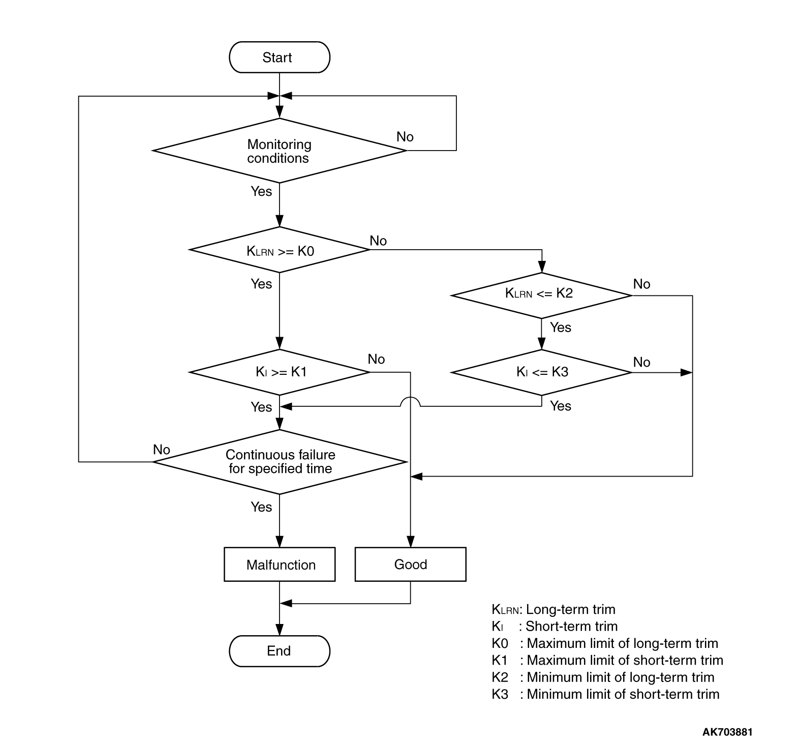
Check Conditions
- Under the closed loop air/fuel ratio control.
- Engine coolant temperature is higher than 76°C (169°F).
- Mass airflow sensor output is 9 g/sec or more.
Judgement Criterion
- Long-term fuel trim has continued to be lower than -12.5 percent for 5
seconds.
or
- Short-term fuel trim has continued to be lower than -10.2
percent for 5 seconds.
Check Conditions
- Under the closed loop air/fuel ratio control.
- Engine coolant temperature is higher than 76°C (169°F).
- Mass airflow sensor output is 9 g/sec or less.
Judgement Criterion
- Long-term fuel trim has continued to be lower than -12.5 percent for 5
seconds.
or
- Short-term fuel trim has continued to be lower than -15.2
percent for 5 seconds.
Check Conditions
- Engine coolant temperature is higher than 76°C (169°F).
- Under the closed loop air/fuel ratio control.
Judgement Criteria
- Long-term fuel trim has continued to be -12.5 percent for 2 seconds.
or
- Short-term fuel trim has continued to be -25.0
percent for 2 seconds.
OBD-II DRIVE CYCLE PATTERN
Refer to Diagnostic Function -
OBD-II Drive Cycle -
Pattern
21 .
TROUBLESHOOTING HINTS (The most likely causes for this code
to be set are:)
- Mass airflow sensor failed.
- Injector failed.
- Incorrect fuel pressure.
- Engine coolant temperature sensor failed.
- Intake air temperature sensor failed.
- Barometric pressure sensor failed.
- Manifold absolute pressure sensor failed.
- ECM failed.
|
|
Required Special Tools:
- MB991958: Scan Tool (M.U.T.-III Sub Assembly)
- MB991824: V.C.I.
- MB991827: USB Cable
- MB991910: Main Harness A
|
|
|
STEP 1. Using scan tool MB991958, check data list item
10: Mass Airflow Sensor.
|

|
| caution |
To prevent damage to scan tool MB991958, always turn the ignition switch to the "LOCK"
(OFF) position before connecting or disconnecting scan tool MB991958.
|
(1)Connect scan tool MB991958 to the data link connector.
(2)Start the engine and run at idle.
(3)Set scan tool MB991958 to the data reading mode for item 10, Mass Airflow Sensor.
(4)Warm up the engine to normal operating temperature: 80°C to 95°C
(176°F to 203°F).
- When idling, between 1,350 and 1,670 millivolts.
- When 2,500 r/min, between 1,620 and 2,020 millivolts.
(5)Turn the ignition switch to the "LOCK" (OFF) position.
Q.
Is the sensor operating properly?
 YES: Go to Step 2. YES: Go to Step 2.
 Refer to DTC P0101 -
Mass Airflow Circuit Range/Performance
Problem , DTC P0102 -
Mass Airflow Circuit Low
Input , DTC P0103 -
Mass Airflow Circuit High
Input . Refer to DTC P0101 -
Mass Airflow Circuit Range/Performance
Problem , DTC P0102 -
Mass Airflow Circuit Low
Input , DTC P0103 -
Mass Airflow Circuit High
Input .
|
|
|
STEP 2. Using scan tool MB991958, check data list item 5: Intake Air
Temperature Sensor.
|
|
|
(1)Turn the ignition switch to the "ON" position.
|
|
|
(2)Set scan tool MB991958 to the data reading mode for item 5, Intake Air Temperature
Sensor.
- The intake air temperature and temperature shown with the
scan tool should approximately match.
|
|
|
(3)Turn the ignition switch to the "LOCK" (OFF) position.
|
|
|
Q.
Is the sensor operating properly?
|
|
|
Go to Step 3.
|
|
|
|
|
|
Refer to DTC P0111 -
Intake Air Temperature Circuit Range/Performance
Problem , DTC P0112 -
Intake Air Temperature Circuit Low
Input , DTC P0113 -
Intake Air Temperature Circuit
High Input .
|
|
|
|
|
|
STEP 3. Using scan tool MB991958, check data list item 6: Engine Coolant
Temperature Sensor.
|
|
|
(1)Turn the ignition switch to the "ON" position.
|
|
|
(2)Set scan tool MB991958 to the data reading mode for item 6, Engine Coolant Temperature
Sensor.
- The engine coolant temperature and temperature shown
with the scan tool should approximately match.
|
|
|
(3)Turn the ignition switch to the "LOCK" (OFF) position.
|
|
|
Q.
Is the sensor operating properly?
|
|
|
Go to Step 4.
|
|
|
|
|
|
Refer to DTC P0116 -
Engine Coolant Temperature Circuit Range/Performance Problem,
DTC P0117 -
Engine Coolant Temperature Circuit Low Input , DTC
P0118 -
Engine Coolant Temperature Circuit High Input .
|
|
|
|
|
|
STEP 4. Using scan tool MB991958, check data list item 8: Manifold
Absolute Pressure Sensor.
|
|
|
(1)Turn the ignition switch to the "ON" position.
|
|
|
(2)Set scan tool MB991958 to the data reading mode for item 8, Manifold Absolute Pressure
Sensor.
- When altitude is 0 m (0 foot), 101 kPa (29.8 in.Hg).
- When altitude is 600 m (1,969 feet), 95 kPa (28.1 in.Hg).
- When altitude is 1,200 m (3,937 feet), 88 kPa (26.0 in.Hg).
- When altitude is 1,800 m (5,906 feet), 81 kPa (23.9 in.Hg).
|
|
|
(3)Start the engine.
- When the engine is idling, 16 -
36 kPa (4.7 -
10.6 in.Hg).
- When the engine is suddenly revved, manifold absolute pressure varies.
|
|
|
(4)Turn the ignition switch to the "LOCK" (OFF) position.
|
|
|
Q.
Is the sensor operating properly?
|
|
|
Go to Step 5.
|
|
|
|
|
|
Refer to DTC P0106 -
Manifold Absolute Pressure Circuit Range/Performance
Problem , DTC P0107 -
Manifold Absolute Pressure
Circuit Low Input , DTC P0108 -
Manifold Absolute
Pressure Circuit High Input .
|
|
|
|
|
|
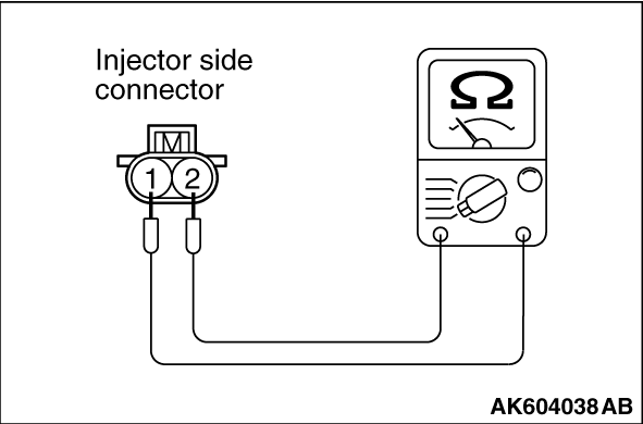
STEP 5. Check the injector.
|
|
|
(1)Disconnect the injector connector B-101, B-102, B-103 and B-104.
|
|
(2)Measure the resistance between each injector side connector terminal No. 1 and No. 2.
Standard value: 10.5 -
13.5 Ω
[at 20°C (68°F)]
Q.
Is the measured resistance between 10.5 and 13.5 Ω
[at 20°C (68°F)]?
Go to Step 6.
Replace the injector. Then go to Step 8.
|
|
|
STEP 6. Check the fuel pressure.
|
|
|
Refer to On-vehicle Service -
Fuel Pressure Test .
|
|
|
Q.
Is the fuel pressure normal?
|
|
|
Go to Step 7.
|
|
|
|
|
|
Repair it. Then go to Step 8.
|
|
|
|
|
|
STEP 7. Replace the injector.
|
|
|
(2)Carry out a test drive with the drive cycle pattern. Refer to Diagnostic Function -
OBD-II
Drive Cycle -
Pattern 21 .
|
|
|
(3)Check the diagnostic trouble code (DTC).
|
|
|
Replace the ECM. When the ECM is replaced, register the ID code. Refer to GROUP
42B, Diagnosis -
ID Code Registration Judgment Table <Vehicles with KOS> or
GROUP 42C, Diagnosis -
ID Codes Registration Judgment Table <Vehicles with WCM> .
Then go to Step 8.
|
|
|
|
|
|
The inspection is complete.
|
|
|
|
|
|
STEP 8. Test the OBD-II drive cycle.
|
|
|
(1)Carry out a test drive with the drive cycle pattern. Refer to Diagnostic Function -
OBD-II
Drive Cycle -
Pattern 21 .
|
|
|
(2)Check the diagnostic trouble code (DTC).
|
|
|
Retry the troubleshooting.
|
|
|
|
|
|
The inspection is complete.
|
|
|
|
)
)
)