![[Previous]](../../../buttons/fprev.png)
![[Next]](../../../buttons/fnext.png)
DTC P0134: Heated
Oxygen Sensor (front) No Activity Detected
Heated Oxygen Sensor (front) No Activity Detected Circuit
- Refer to DTC P0131 -
Heated Oxygen Sensor (Front) Circuit Low Voltage
 .
.
- Refer to DTC P0201 -
Injector Circuit-cylinder 1 .
- Refer to DTC P0202 -
Injector Circuit-cylinder 2 .
- Refer to DTC P0203 -
Injector Circuit-cylinder 3 .
- Refer to DTC P0204 -
Injector Circuit-cylinder 4 .
CIRCUIT OPERATION
- Refer to DTC P0131 -
Heated Oxygen Sensor (Front) Circuit Low Voltage .
- Refer to DTC P0201 -
Injector Circuit-cylinder 1 .
- Refer to DTC P0202 -
Injector Circuit-cylinder 2 .
- Refer to DTC P0203 -
Injector Circuit-cylinder 3 .
- Refer to DTC P0204 -
Injector Circuit-cylinder 4 .
TECHNICAL DESCRIPTION
- The ECM effects air/fuel ratio feedback control
in accordance with the signals from the heated oxygen sensor (front).
- If the heated oxygen sensor (front) has deteriorated, corrections will be made by
the heated oxygen sensor (rear).
- DTC P0134 becomes stored in memory if a failure is detected in the above air/fuel
ratio feedback control system.
DESCRIPTIONS OF MONITOR METHODS
Heated oxygen sensor (front) output voltage does not
cross lean/rich criteria (about 0.5 volt) within specified period.
MONITOR EXECUTION
MONITOR EXECUTION CONDITIONS (Other monitor and Sensor)
Other Monitor (There is no temporary DTC stored in memory
for the item monitored below)
Sensor (The sensor below is determined to be normal)
- Mass airflow sensor
- Engine coolant temperature sensor
- Intake air temperature sensor
- Barometric pressure sensor
- Throttle position sensor
DTC SET CONDITIONS
Logic Flow Chart
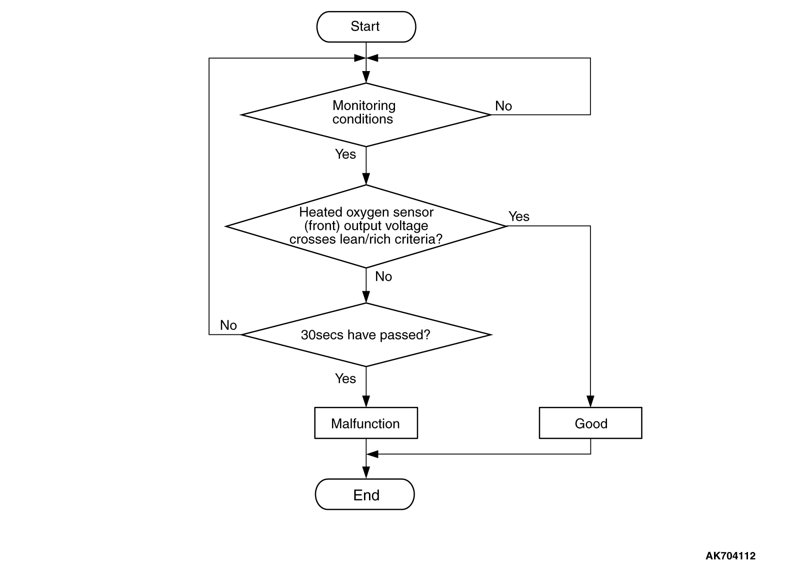
Check Conditions
- 20 seconds or more have passed since the engine starting sequence was completed.
- Engine coolant temperature is higher than 7°C (45°F).
- Engine speed is higher than 1,188 r/min.
- Volumetric efficiency is higher than 30 percent.
- Throttle position sensor output voltage is lower than 4 volts.
- Except while fuel is being shut off.
- Monitoring time: 30 seconds.
Judgement Criterion
- Heated oxygen sensor (front) output voltage does not get across lean/rich criteria
(about 0.5 volt) within about 30 seconds.
OBD-II DRIVE CYCLE PATTERN
Refer to Diagnostic Function -
OBD-II Drive
Cycle -
Pattern 12 .
TROUBLESHOOTING HINTS (The most likely causes for this code to be set are: )
- Heated oxygen sensor (front) deteriorated.
- Harness damage in heated oxygen sensor (front) output line.
- Heated oxygen sensor (rear) deteriorated.
| note |
When the heated oxygen sensor (front) begins to deteriorate, the heated oxygen sensor
output voltage will deviate from the voltage when the sensor was new (normally 0.5 volt at stoichiometric
ratio). This deviation will be corrected by the heated oxygen sensor (rear).
If the heated oxygen sensor (rear) responds poorly because it has deteriorated, it will
improperly correct the heated oxygen sensor (front). Thus, even when closed loop control is being
effected, the fluctuation of the heated oxygen sensor (front) output voltage decreases, without
intersecting with 0.5 volt. As a result, there is a possibility of DTC P0134 becoming registered.
|
- Open circuit in injector.
- Harness damage in injector circuit.
- Connector damage.
- ECM failed.
- Exhaust leak.
- Air drawn in from gaps in gasket, seals, etc.
- Incorrect fuel pressure.
|
|
Required Special Tools:
- MB991958: Scan Tool (M.U.T.-III Sub Assembly)
- MB991824: V.C.I.
- MB991827: USB Cable
- MB991910: Main Harness A
- MB991658: Test Harness
|
|
|
STEP 1. Using scan tool MB991958, check data list item
AD: Heated Oxygen Sensor (rear).
|

|
| caution |
To prevent damage to scan tool MB991958, always turn the ignition switch to the "LOCK"
(OFF) position before connecting or disconnecting scan tool MB991958.
|
(1)Connect scan tool MB991958 to the data link connector.
(2)Start the engine and run at idle.
(3)Set scan tool MB991958 to the data reading mode for item AD, Heated Oxygen Sensor
(rear).
- Transaxle: 2nd speed (CVT: "L" range).
- Drive with wide open throttle
- Engine: 3,500 r/min
- The output voltage should be between 0.6 and 1.0 volt.
(4)Turn the ignition switch to the "LOCK" (OFF) position.
Q.
Is the sensor operating properly?
 Go to Step 2. Go to Step 2.
 Refer to DTC P0137 -
Heated Oxygen Sensor (rear) Circuit Low Voltage ,
DTC P0138 -
Heated Oxygen Sensor (rear) Circuit High Voltage ,
DTC P0139 -
Heated Oxygen Sensor (rear) Circuit Slow Response , P0140 -
Heated
Oxygen Sensor (rear) Circuit No Activity Detected . Refer to DTC P0137 -
Heated Oxygen Sensor (rear) Circuit Low Voltage ,
DTC P0138 -
Heated Oxygen Sensor (rear) Circuit High Voltage ,
DTC P0139 -
Heated Oxygen Sensor (rear) Circuit Slow Response , P0140 -
Heated
Oxygen Sensor (rear) Circuit No Activity Detected .
|
|
|
STEP 2. Check for exhaust leak.
|
|
|
Q.
Are there any abnormalities?
|
|
|
Repair it. Then go to Step 12.
|
|
|
|
|
|
Go to Step 3.
|
|
|
|
|
|
STEP 3. Check for intake system vacuum leak.
|
|
|
Q.
Are there any abnormalities?
|
|
|
Repair it. Then go to Step 12.
|
|
|
|
|
|
Go to Step 4.
|
|
|
|
|
|
STEP 4. Check harness connector C-44 at the heated oxygen sensor (front)
for damage.
|
|
|
Q.
Is the harness connector in good condition?
|
|
|
Go to Step 5.
|
|
|
|
|
|
Repair or replace it. Refer to GROUP 00E, Harness Connector Inspection .
Then go to Step 12.
|
|
|
|
|
|
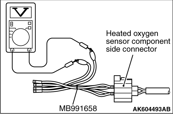
STEP 5. Check the heated oxygen sensor (front).
|
|
|
(1)Disconnect the heated oxygen sensor (front) connector C-44 and connect test harness
special tool MB991658 to the connector on the heated oxygen sensor (front) side.
|
|
|
(2)Warm up the engine until engine coolant temperature reaches 80°C (176°F)
or higher.
|
|
|
(3)Rev the engine for 5 minutes or more with the engine speed of 2,500 r/min.
|
|
(4)Connect a digital voltage meter between terminal No. 3 and terminal No. 4.
(5)While repeatedly revving the engine, measure the heated oxygen sensor (front) output voltage.
(6)Standard value: 0.6 -
1.0 V
| caution |
- Be very careful when connecting the jumper wires;
incorrect connection can damage the heated oxygen sensor.
- Be careful the heater can be damaged if a voltage beyond 8 volts is applied to the
heated oxygen sensor heater.
|
| note |
If the temperature of sensing area does not reach the high temperature [of approximately 400°C
(752°F) or more]
even though the heated oxygen sensor is normal, the output
voltage would be possibly low in spite of the rich air/fuel ratio. Therefore, if the output
voltage is low, use a jumper wire to connect the terminal No. 1 and the terminal No. 2 of the
heated oxygen sensor with the positive terminal and the negative terminal of 8 volts power supply
respectively, then check again.
|
Q.
Is the measured voltage between 0.6 and 1.0 volt?
Go to Step 6.
Replace the heated oxygen sensor (front). Then go to Step 12.
|
|
|
STEP 6. Check harness connector B-101, B-102, B-103, and B-104 at
injector for damage.
|
|
|
Q.
Is the harness connector in good condition?
|
|
|
Go to Step 7.
|
|
|
|
|
|
Repair or replace it. Refer to GROUP 00E, Harness Connector Inspection .
Then go to Step 12.
|
|
|
|
|
|
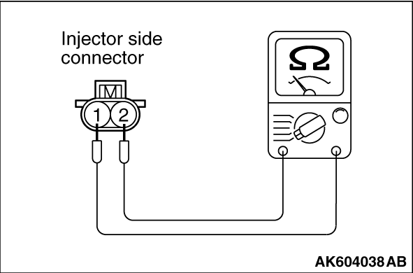
STEP 7. Check the injectors.
|
|
|
(1)Disconnect each injector connector.
|
|
(2)Measure the resistance between injector side connector terminal No. 1 and No. 2.
Standard value: 10.5 -
13.5 Ω
[at 20°C (68°F)]
Q.
Is the measured resistance between 10.5 and 13.5 Ω
[at 20°C (68°F)]?
Go to Step 8.
Replace the injector. Then go to Step 12.
|
|
|
STEP 8. Check harness connector B-108 at ECM for damage.
|
|
|
Q.
Is the harness connector in good condition?
|
|
|
Go to Step 9.
|
|
|
|
|
|
Repair or replace it. Refer to GROUP 00E, Harness Connector Inspection .
Then go to Step 12.
|
|
|
|
|
|
STEP 9. Check for harness damage between heated oxygen sensor (front)
connector C-44 (terminal No. 3) and ECM connector B-108 (terminal No. 38).
|
|
|
| note |
Check harness after checking intermediate connector A-10. If intermediate connector is damaged,
repair or replace it. Refer to GROUP 00E, Harness Connector Inspection .
Then go to Step 12.
|
|
|
|
Q.
Is the harness wire in good condition?
|
|
|
Go to Step 10.
|
|
|
|
|
|
Repair it. Then go to Step 12.
|
|
|
|
|
|
STEP 10. Check for harness damage between injector connector and ECM
connector.
|
|
|
- Check the harness wire between injector connector
B-101 (terminal No. 2) and ECM connector B-108 (terminal No. 2) when checking No. 1 cylinder.
- Check the harness wire between injector connector B-102 (terminal No. 2) and ECM
connector B-108 (terminal No. 3) when checking No. 2 cylinder.
- Check the harness wire between injector connector B-103 (terminal No. 2) and ECM
connector B-108 (terminal No. 18) when checking No. 3 cylinder.
- Check the harness wire between injector connector B-104 (terminal No. 2) and ECM
connector B-108 (terminal No. 19) when checking No. 4 cylinder.
|
|
|
Q.
Is the harness wire in good condition?
|
|
|
Go to Step 11.
|
|
|
|
|
|
Repair it. Then go to Step 12.
|
|
|
|
|
|
STEP 11. Check the fuel pressure.
|
|
|
Refer to On-vehicle Service -
Fuel Pressure Test .
|
|
|
Q.
Is the fuel pressure normal?
|
|
|
Replace the ECM. When the ECM is replaced, register the ID code. Refer to GROUP
42B, Diagnosis -
ID Code Registration Judgment Table <Vehicles with KOS> or
GROUP 42C, Diagnosis -
ID Codes Registration Judgment Table <Vehicles with WCM> .
Then go to Step 12.
|
|
|
|
|
|
Repair it. Then go to Step 12.
|
|
|
|
|
|
STEP 12. Test the OBD-II drive cycle.
|
|
|
(1)Carry out a test drive with the drive cycle pattern. Refer to Diagnostic Function -
OBD-II
Drive Cycle -
Pattern 12 .
|
|
|
(2)Check the diagnostic trouble code (DTC).
|
|
|
Retry the troubleshooting.
|
|
|
|
|
|
The inspection is complete.
|
|
|
|
)
)
)
)