![[Previous]](../../../buttons/fprev.png)
![[Next]](../../../buttons/fnext.png)
DTC P0107: Manifold
Absolute Pressure Circuit Low Input
CIRCUIT OPERATION
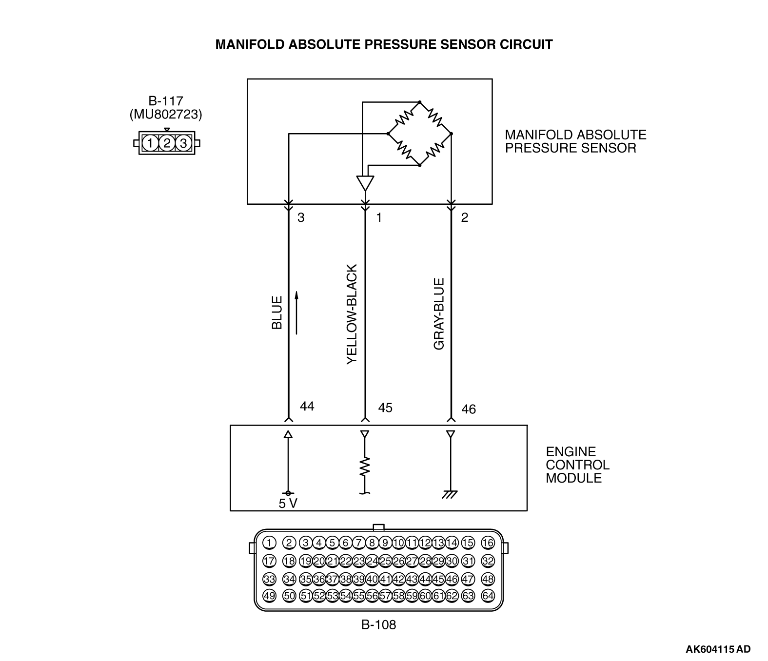
- A 5-volt voltage is supplied to the manifold absolute
pressure sensor power terminal (terminal No. 3) from the ECM (terminal No. 44). The ground terminal
(terminal No. 2) is grounded with ECM (terminal No. 46).
- A voltage that is proportional to the intake manifold pressure is sent to the ECM
(terminal No. 45) from the manifold absolute pressure sensor output terminal (terminal No. 1).
TECHNICAL DESCRIPTION
- The manifold absolute pressure sensor outputs a voltage
which corresponds to the intake manifold pressure.
- The ECM checks whether this voltage is within a specified range.
DESCRIPTIONS OF MONITOR METHODS
Manifold absolute pressure sensor output voltage is out
of specified range.
MONITOR EXECUTION
MONITOR EXECUTION CONDITIONS (Other monitor and Sensor)
Other Monitor (There is no temporary DTC stored in memory
for the item monitored below)
Sensor (The sensor below is determined to be normal)
- Mass airflow sensor
- Engine coolant temperature sensor
- Intake air temperature sensor
- Barometric pressure sensor
- Throttle position sensor
DTC SET CONDITIONS
Logic Flow Chart
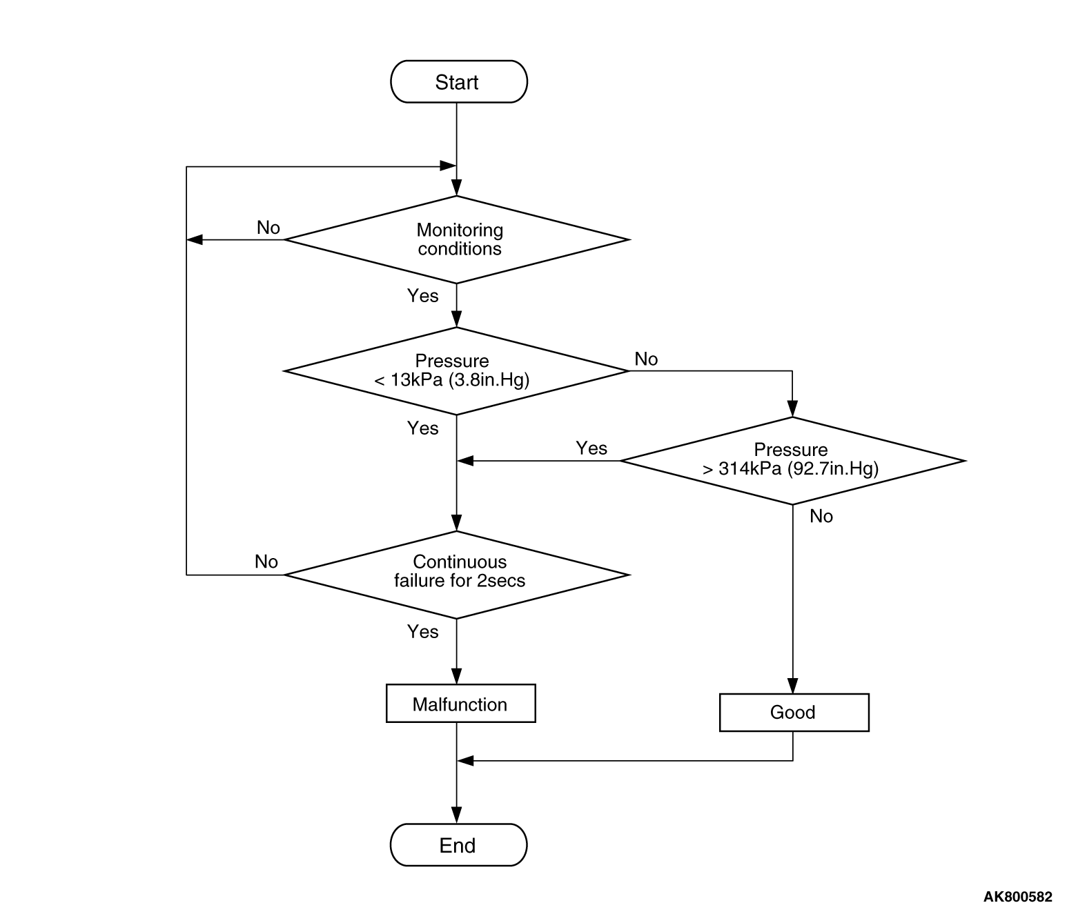
Check Conditions
- More than 8 minutes have passed since the engine starting sequence was completed,
when the engine coolant temperature at engine start is less than 0°C (32°F).
- Volumetric efficiency is more than 20 percent.
Judgement Criterion
- Manifold absolute pressure sensor output voltage is less than 0.2 volt [corresponding
to a manifold absolute pressure of 13 kPa (3.8 in.Hg)]
for 2 seconds.
FAIL-SAFE AND BACKUP FUNCTION
OBD-II DRIVE CYCLE PATTERN
Refer to Diagnostic Function -
OBD-II Drive Cycle -
Pattern
6  .
.
TROUBLESHOOTING HINTS (The most likely causes for this code to be set are:)
- Manifold absolute pressure sensor failed.
- Open or shorted manifold absolute pressure sensor circuit, harness damage or connector damage.
- ECM failed.
|
|
Required Special Tools:
- MB991958: Scan Tool (M.U.T.-III Sub Assembly)
- MB991824: V.C.I.
- MB991827: USB Cable
- MB991910: Main Harness A
- MB992110: Power Plant ECU Check Harness
|
|
|
STEP 1. Using scan tool MB991958, check data list item
8: Manifold Absolute Pressure Sensor.
|

|
| caution |
To prevent damage to scan tool MB991958, always turn the ignition switch to the "LOCK"
(OFF) position before connecting or disconnecting scan tool MB991958.
|
(1)Connect scan tool MB991958 to the data link connector.
(2)Turn the ignition switch to the "ON" position.
(3)Set scan tool MB991958 to the data reading mode for item 8, Manifold Absolute Pressure
Sensor.
- When altitude is 0 m (0 foot), 101 kPa (29.8 in.Hg).
- When altitude is 600 m (1,969 feet), 95 kPa (28.1 in.Hg).
- When altitude is 1,200 m (3,937 feet), 88 kPa (26.0 in.Hg).
- When altitude is 1,800 m (5,906 feet), 81 kPa (23.9 in.Hg).
(4)Start the engine.
- When the engine is idling, 31 -
45 kPa (9.2 -
13.3
in.Hg).
- When the engine is suddenly revved, manifold absolute pressure varies.
(5)Turn the ignition switch to the "LOCK" (OFF) position.
Q.
Is the sensor operating properly?
 It can be assumed that this malfunction is intermittent. Refer to GROUP 00, How
to Use Troubleshooting/Inspection Service Points -
How to Cope with Intermittent
Malfunctions . It can be assumed that this malfunction is intermittent. Refer to GROUP 00, How
to Use Troubleshooting/Inspection Service Points -
How to Cope with Intermittent
Malfunctions .
 Go to Step 2. Go to Step 2.
|
|
|
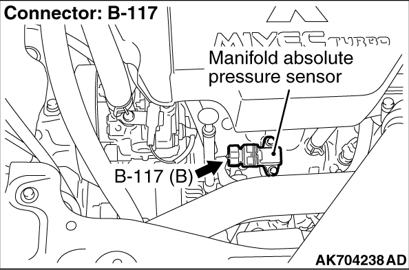
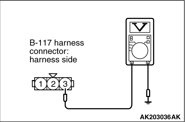
STEP 2. Measure the sensor supply voltage at manifold absolute pressure
sensor connector B-117 by backprobing.
|
|
|
(1)Do not disconnect the connector B-117.
|
|
|
(2)Turn the ignition switch to the "ON" position.
|
|
(3)Measure the voltage between terminal No. 3 and ground by backprobing.
- Voltage should be between 4.9 and 5.1 volts.
(4)Turn the ignition switch to the "LOCK" (OFF) position.
Q.
Is the measured voltage between 4.9 and 5.1 volts?
Go to Step 8.
Go to Step 3.
|
|
|
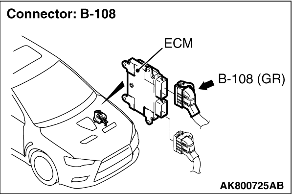
STEP 3. Check harness connector B-108 at ECM for damage.
|
|
|
Q.
Is the harness connector in good condition?
|
|
|
Go to Step 4.
|
|
|
|
|
|
Repair or replace it. Refer to GROUP 00E, Harness Connector Inspection .
Then go to Step 12.
|
|
|
|
|
|
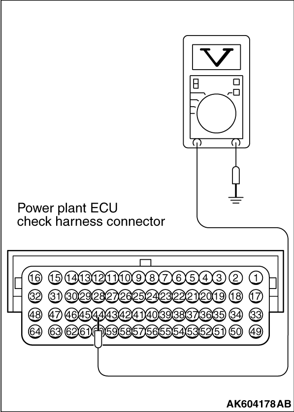
STEP 4. Measure the sensor supply voltage at ECM connector B-108 by
using power plant ECU check harness special tool MB992110.
|
|
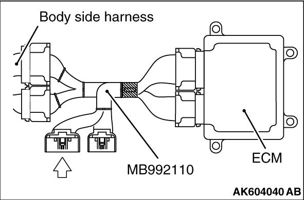
(1)Disconnect all ECM connectors. Connect the power plant ECU check harness special
tool MB992110 between the separated connectors.
(2)Turn the ignition switch to the "ON" position.
|
|
(3)Measure the voltage between terminal No. 44 and ground.
- Voltage should be between 4.9 and 5.1 volts.
(4)Turn the ignition switch to the "LOCK" (OFF) position.
Q.
Is the measured voltage between 4.9 and 5.1 volts?
Go to Step 7.
Go to Step 5.
|
|
|
STEP 5. Check harness connector B-117 at manifold absolute pressure
sensor for damage.
|
|
|
Q.
Is the harness connector in good condition?
|
|
|
Go to Step 6.
|
|
|
|
|
|
Repair or replace it. Refer to GROUP 00E, Harness Connector Inspection .
Then go to Step 12.
|
|
|
|
|
|
STEP 6. Check for short circuit to ground between manifold absolute
pressure sensor connector B-117 (terminal No. 3) and ECM connector B-108 (terminal No. 44).
|
|
|
Q.
Is the harness wire in good condition?
|
|
|
Go to Step 11.
|
|
|
|
|
|
Repair it. Then go to Step 12.
|
|
|
|
|
|
STEP 7. Check harness connector B-117 at manifold absolute pressure
sensor for damage.
|
|
|
Q.
Is the harness connector in good condition?
|
|
|
Repair harness wire between manifold absolute pressure sensor connector B-117
(terminal No. 3) and ECM connector B-108 (terminal No. 44) because of open circuit. Then go
to Step 12.
|
|
|
|
|
|
Repair or replace it. Refer to GROUP 00E, Harness Connector Inspection .
Then go to Step 12.
|
|
|
|
|
|
STEP 8. Check harness connector B-117 at manifold absolute pressure
sensor and harness connector B-108 at ECM for damage.
|
|
|
Q.
Are the harness connectors in good condition?
|
|
|
Go to Step 9.
|
|
|
|
|
|
Repair or replace them. Refer to GROUP 00E, Harness Connector Inspection .
Then go to Step 12.
|
|
|
|
|
|
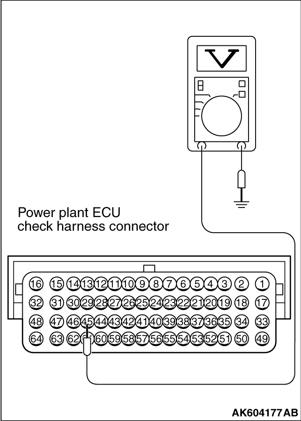
STEP 9. Measure the sensor output voltage at ECM connector B-108 by
using power plant ECU check harness special tool MB992110.
|
|
(1)Disconnect all ECM connectors. Connect the power plant ECU check harness special
tool MB992110 between the separated connectors.
(2)Turn the ignition switch to the "ON" position.
|
|
(3)Measure the voltage between terminal No. 45 and ground.
- When altitude is 0 m (0 foot), voltage should be between 1.2
and 1.8 volts.
- When altitude is 600 m (1,969 feet), voltage should be between 1.1 and 1.7 volts.
- When altitude is 1,200 m (3,937 feet), voltage should be between 1.0 and 1.6 volts.
- When altitude is 1,800 m (5,906 feet), voltage should be between 0.9 and 1.5 volts.
(4)Turn the ignition switch to the "LOCK" (OFF) position.
Q.
Is the measured voltage normal?
Go to Step 11.
Go to Step 10.
|
|
|
STEP 10. Check for open circuit and short circuit to ground between
manifold absolute pressure sensor connector B-117 (terminal No. 1) and ECM connector B-108 (terminal
No. 45).
|
|
|
Q.
Is the harness wire in good condition?
|
|
|
Replace the manifold absolute pressure sensor. Then go to Step 12.
|
|
|
|
|
|
Repair it. Then go to Step 12.
|
|
|
|
|
|
STEP 11. Using scan tool MB991958, check data list item 8: Manifold
Absolute Pressure Sensor.
|
|
|
(1)Turn the ignition switch to the "ON" position.
|
|
|
(2)Set scan tool MB991958 to the data reading mode for item 8, Manifold Absolute Pressure
Sensor.
- When altitude is 0 m (0 foot), 101 kPa (29.8 in.Hg).
- When altitude is 600 m (1,969 feet), 95 kPa (28.1 in.Hg).
- When altitude is 1,200 m (3,937 feet), 88 kPa (26.0 in.Hg).
- When altitude is 1,800 m (5,906 feet), 81 kPa (23.9 in.Hg).
|
|
|
(3)Start the engine.
- When the engine is idling, 31 -
45 kPa (9.2 -
13.3
in.Hg).
- When the engine is suddenly revved, manifold absolute pressure varies.
|
|
|
(4)Turn the ignition switch to the "LOCK" (OFF) position.
|
|
|
Q.
Is the sensor operating properly?
|
|
|
It can be assumed that this malfunction is intermittent. Refer to GROUP 00, How
to Use Troubleshooting/Inspection Service Points -
How to Cope with Intermittent
Malfunctions .
|
|
|
|
|
|
Replace the ECM. When the ECM is replaced, register the ID code. Refer to GROUP
42B, Diagnosis -
ID Code Registration Necessity Judgment Table <Vehicles with KOS> or
GROUP 42C, Diagnosis -
ID Codes Registration Judgment Table <Vehicles with WCM> .
Then go to Step 12.
|
|
|
|
|
|
STEP 12. Test the OBD-II drive cycle.
|
|
|
(1)Carry out a test drive with the drive cycle pattern. Refer to Diagnostic Function -
OBD-II
Drive Cycle -
Pattern 6 .
|
|
|
(2)Check the diagnostic trouble code (DTC).
|
|
|
Retry the troubleshooting.
|
|
|
|
|
|
The inspection is complete.
|
|
|
|
)
)
)
)
)
)
)
)
)