[Previous] [Next]

DIAGNOSTIC FUNCTION


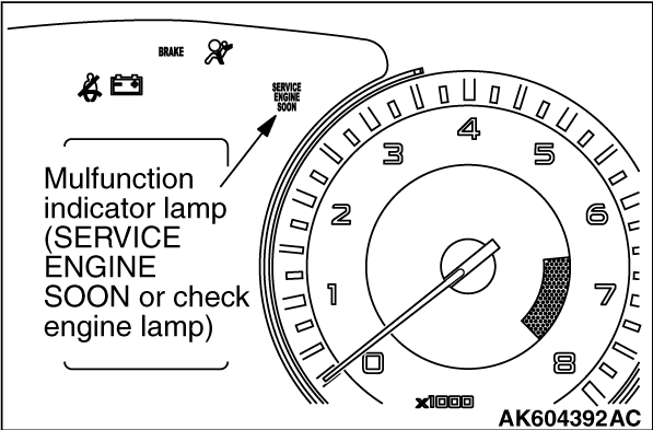
MALFUNCTION INDICATOR LAMP (SERVICE ENGINE SOON OR CHECK ENGINE LAMP)


Among the on-board diagnostic items, Malfunction Indicator Lamp (SERVICE ENGINE SOON or Check Engine Lamp) illuminates to notify the driver of an emission control malfunction.
However, when an irregular signal returns to normal and the engine control module judges that it has returned to normal, the Malfunction Indicator Lamp (SERVICE ENGINE SOON or Check Engine Lamp) will switch off.
There are two methods for checking the Malfunction Indicator Lamp (SERVICE ENGINE SOON or Check Engine Lamp) burn out: When the ignition switch is in ON position, the Malfunction Indicator Lamp (SERVICE ENGINE SOON or Check Engine Lamp) is illuminated, and then extinguished few seconds later. When the ignition switch is in ON position and the engine starts, the Malfunction Indicator Lamp (SERVICE ENGINE SOON or Check Engine Lamp) is extinguished.
note When the Transmission Control Module (TCM) detects malfunctions related to the CVT, the Malfunction indicator Lamp (SERVICE ENGINE SOON or Check Engine Lamp) is also illuminated.

Items Indicated by the Malfunction Indicator Lamp (SERVICE ENGINE SOON or Check Engine Lamp)


DTC
ITEM
P0010
Intake engine oil control valve circuit
P0011
Intake variable valve timing system target error
P0013
Exhaust engine oil control valve circuit
P0014
Exhaust variable valve timing system target error
P0016
Crankshaft/camshaft (intake) position sensor phase problem
P0017
Crankshaft/camshaft (exhaust) position sensor phase problem
P0031
Heated oxygen sensor (front) heater circuit low
P0032
Heated oxygen sensor (front) heater circuit high
P0037
Heated oxygen sensor (rear) heater circuit low
P0038
Heated oxygen sensor (rear) heater circuit high
P0069
Abnormal correlation between manifold absolute pressure sensor and barometric pressure sensor
P0101*1
Mass airflow circuit range/performance problem
P0102*1
Mass airflow circuit low input
P0103*1
Mass airflow circuit high input
P0106
Manifold absolute pressure circuit range/performance problem
P0107
Manifold absolute pressure circuit low input
P0108
Manifold absolute pressure circuit high input
P0111*1
Intake air temperature circuit range/performance problem
P0112*1
Intake air temperature circuit low input
P0113*1
Intake air temperature circuit high input
P0116*1
Engine coolant temperature circuit range/performance problem
P0117*1
Engine coolant temperature circuit low input
P0118*1
Engine coolant temperature circuit high input
P0122*1
Throttle position sensor (main) circuit low input
P0123*1
Throttle position sensor (main) circuit high input
P0125*1
Insufficient coolant temperature for closed loop fuel control
P0128
Coolant thermostat (coolant temperature below thermostat regulating temperature)
P0131
Heated oxygen sensor (front) circuit low voltage
P0132
Heated oxygen sensor (front) circuit high voltage
P0133
Heated oxygen sensor (front) circuit slow response
P0134*1
Heated oxygen sensor (front) circuit no activity detected
P0137
Heated oxygen sensor (rear) circuit low voltage
P0138
Heated oxygen sensor (rear) circuit high voltage
P0139
Heated oxygen sensor (rear) circuit slow response
P0140
Heated oxygen sensor (rear) circuit no activity detected
P0171
System too lean
P0172
System too rich
P0181
Fuel tank temperature sensor circuit range/performance
P0182
Fuel tank temperature sensor circuit low input
P0183
Fuel tank temperature sensor circuit high input
P0201
Injector circuit - cylinder 1
P0202
Injector circuit - cylinder 2
P0203
Injector circuit - cylinder 3
P0204
Injector circuit - cylinder 4
P0222*1
Throttle position sensor (sub) circuit low input
P0223*1
Throttle position sensor (sub) circuit high input
P0300*2
Random/multiple cylinder misfire detected
P0301*2
Cylinder 1 misfire detected
P0302*2
Cylinder 2 misfire detected
P0303*2
Cylinder 3 misfire detected
P0304*2
Cylinder 4 misfire detected
P0327
Knock sensor circuit low
P0328
Knock sensor circuit high
P0335*1
Crankshaft position sensor circuit
P0340*1
Intake camshaft position sensor circuit
P0365*1
Exhaust camshaft position sensor circuit
P0401
Exhaust gas recirculation flow insufficient detected
P0420
Warm up catalyst efficiency below threshold
P0441
Evaporative emission control system incorrect purge flow
P0442
Evaporative emission control system leak detected (small leak)
P0443
Evaporative emission control system purge control valve circuit
P0446
Evaporative emission control system vent control circuit
P0450
Evaporative emission control system pressure sensor malfunction
P0451
Evaporative emission control system pressure sensor range/performance
P0452
Evaporative emission control system pressure sensor low input
P0453
Evaporative emission control system pressure sensor high input
P0455
Evaporative emission control system leak detected (gross leak)
P0456
Evaporative emission control system leak detected (very small leak)
P0461
Fuel level sensor circuit range/performance
P0462
Fuel level sensor circuit low input
P0463
Fuel level sensor circuit high input
P0489
EGR valve (stepper motor) circuit malfunction (ground short)
P0490
EGR valve (stepper motor) circuit malfunction (battery short)
P0500*1
Vehicle speed sensor malfunction <M/T>
P0506
Idle control system RPM lower than expected
P0507
Idle control system RPM higher than expected
P050B
Ignition timing retard insufficient
P0551
Power steering pressure switch circuit range/performance
P0554
Power steering pressure switch circuit intermittent
P0603*1
EEPROM malfunction
P0606*1
Engine control module main processor malfunction
P0630*1
Vehicle Identification Number (VIN) malfunction
P0638*1
Throttle actuator control motor circuit range/ performance
P0642*1
Throttle position sensor power supply
P0657*1
Throttle actuator control motor relay circuit malfunction
P1233*1
Throttle position sensor (main) plausibility
P1234*1
Throttle position sensor (sub) plausibility
P1235*1
Mass airflow sensor plausibility
P1236*1
A/D converter
P1237*1
Accelerator pedal position sensor plausibility
P1238*1
Mass airflow sensor plausibility (torque monitor)
P1239*1
Engine RPM plausibility
P1241*1
Torque monitor
P1506
Idle control system RPM lower than expected at low temperature
P1507
Idle control system RPM higher than expected at low temperature
P1590*1
TCM to ECM communication error in torque reduction request <CVT>
P1603*1
Battery backup circuit malfunction
P1676*1
Variant coding
P2100*1
Throttle actuator control motor circuit (open)
P2101*1
Throttle actuator control motor magneto malfunction
P2122*1
Accelerator pedal position sensor (main) circuit low input
P2123*1
Accelerator pedal position sensor (main) circuit high input
P2127*1
Accelerator pedal position sensor (sub) circuit low input
P2128*1
Accelerator pedal position sensor (sub) circuit high input
P2135*1
Throttle position sensor (main and sub) range/performance problem
P2138*1
Accelerator pedal position sensor (main and sub) range/performance problem
P2195
Heated oxygen sensor (front) inactive
P2228*1
Barometric pressure circuit low input
P2229*1
Barometric pressure circuit high input
P2252
Heated oxygen sensor offset circuit low voltage
P2253
Heated oxygen sensor offset circuit high voltage
U0101*1
TCM time-out <CVT>
U0141*1
ETACS-ECU time-out
U1180*1
Combination meter time-out
note If the Malfunction Indicator Lamp (SERVICE ENGINE SOON or Check Engine Lamp) illuminates because of a malfunction of the engine control module (ECM), communication between the scan tool MB991958 (M.U.T.-III sub assembly) and the ECM is impossible. In this case, the diagnostic trouble code cannot be read.
note After the ECM has detected a malfunction, the Malfunction Indicator Lamp (SERVICE ENGINE SOON or Check Engine Lamp) illuminates when the engine is next turned on and the same malfunction is re-detected. However, for items marked with a "*1" in the DTC NO. column, the Malfunction Indicator Lamp (SERVICE ENGINE SOON or Check Engine Lamp) illuminates only on the first detection of the malfunction.
note The codes marked with a "*2" in the diagnosis code number column have the following two conditions for illuminating the Malfunction Indicator Lamp (SERVICE ENGINE SOON or Check Engine Lamp).

note After the Malfunction Indicator Lamp (SERVICE ENGINE SOON or Check Engine Lamp) illuminates, it will be switched off under the following conditions.


HOW TO CONNECT THE SCAN TOOL (M.U.T.-III)


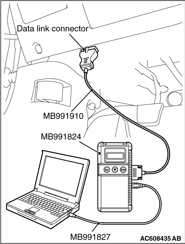
Required Special Tools:
  • MB991958: Scan Tool (M.U.T.-III Sub Assembly)

    • MB991824: V.C.I.
    • MB991827: USB Cable
    • MB991910: Main Harness A
caution To prevent damage to scan tool MB991958, always turn the ignition switch to the "LOCK" (OFF) position before connecting or disconnecting scan tool MB991958.

1.Ensure that the ignition switch is at the "LOCK" (OFF) position.
2.Start up the personal computer.
3.Connect special tool MB991827 to special tool MB991824 and the personal computer.
4.Connect special tool MB991910 to special tool MB991824.
5.Connect special tool MB991910 to the data link connector.
6.Turn the power switch of special tool MB991824 to the "ON" position.
note When the special tool MB991824 is energized, special tool MB991824 indicator light will be illuminated in a green color.
7.Start the M.U.T.-III system on the personal computer.
note Disconnecting the scan tool MB991958 is the reverse of the connecting sequence, making sure that the ignition switch is at the "LOCK" (OFF) position.

HOW TO READ AND ERASE DIAGNOSTIC TROUBLE CODES.


Required Special Tools:
  • MB991958: Scan Tool (M.U.T.-III Sub Assembly)

    • MB991824: V.C.I.
    • MB991827: USB Cable
    • MB991910: Main Harness A
caution To prevent damage to scan tool MB991958, always turn the ignition switch to the "LOCK" (OFF) position before connecting or disconnecting scan tool MB991958.

1.Connect scan tool MB991958 to the data link connector.
2.Turn the ignition switch to the "ON" position.
3.Select "System select."
4.Choose "from 2006 MY" under "MODEL YEAR".
5.Check that "Vehicle Information" contents are correct.
6.Choose "MFI".
7.Select "Diagnostic Trouble Code"
8.If a DTC is set, it is shown.
9.Choose "Erase DTCs" to erase the DTC.

HOW TO READ DATA LIST


Required Special Tools:
  • MB991958: Scan Tool (M.U.T.-III Sub Assembly)

    • MB991824: V.C.I.
    • MB991827: USB Cable
    • MB991910: Main Harness A
caution To prevent damage to scan tool MB991958, always turn the ignition switch to the "LOCK" (OFF) position before connecting or disconnecting scan tool MB991958.

1.Connect scan tool MB991958 to the data link connector.
2.Turn the ignition switch to the "ON" position.
3.Select "System select."
4.Choose "from 2006 MY" under "MODEL YEAR".
5.Check that "Vehicle Information" contents are correct.
6.Choose "MFI".
7.Select "Data List."
8.Choose an appropriate item and select the "OK" button.

HOW TO PERFORM ACTUATOR TEST


Required Special Tools:
  • MB991958: Scan Tool (M.U.T.-III Sub Assembly)

    • MB991824: V.C.I.
    • MB991827: USB Cable
    • MB991910: Main Harness A
caution To prevent damage to scan tool MB991958, always turn the ignition switch to the "LOCK" (OFF) position before connecting or disconnecting scan tool MB991958.

1.Connect scan tool MB991958 to the data link connector.
2.Turn the ignition switch to the "ON" position.
3.Select "System select."
4.Choose "from 2006 MY" under "MODEL YEAR".
5.Check that "Vehicle Information" contents are correct.
6.Choose "MFI".
7.Select "Actuator Test."
8.Choose an appropriate item and select the "OK" button.

HOW TO DIAGNOSE THE CAN BUS LINES


Required Special Tools:
  • MB991958: Scan Tool (M.U.T.-III Sub Assembly)

    • MB991824: V.C.I.
    • MB991827: USB Cable
    • MB991910: Main Harness A
caution To prevent damage to scan tool MB991958, always turn the ignition switch to the "LOCK" (OFF) position before connecting or disconnecting scan tool MB991958.

1.Connect scan tool MB991958 to the data link connector.
2.Turn the ignition switch to the "ON" position.
3.Select "CAN bus diagnosis" from the start-up screen.
4.When the vehicle information is displayed, confirm that it matches the vehicle whose CAN bus lines will be diagnosed.

  • If they matches, go to step 8.
  • If not, go to step 5.
5.Select the "view vehicle information" button.
6.Enter the vehicle information and select the "OK" button.
7.When the vehicle information is displayed, confirm again that it matches the vehicle whose CAN bus lines will be diagnosed.

  • If they matches, go to step 8.
  • If not, go to step 5.
8.Select the "OK" button.
9.When the optional equipment screen is displayed, choose the one which the vehicle is fitted with, and then select the "OK" button.

PROVISIONAL DTCs [OBD-II Test Mode - Results (Mode 7)]


The general scan tool will display the Provisional DTCs reported by ECM if the ECM detects some malfunction for "Misfire", "Fuel System" and "Comprehensive" monitoring during a SINGLE Driving Cycle. The intended use of this data is to assist the technician after a vehicle repair, and after clearing diagnostic information, by reporting test result after a SINGLE Driving Cycle. Note that the test results reported by this mode do not necessarily indicate a faulty component/system. If test results indicate a failure after ADDITIONAL (consecutive) driving, then the Malfunction Indicator Lamp (SERVICE ENGINE SOON or Check Engine Lamp) will be illuminated and a DTC will set.

MODE 6 REFERENCE TABLE


The engine control module (ECM) monitors the condition of emission control system.
By selecting MODE 6 using scan tool, Test Result and Limit Value (minimum) *1 or (maximum) *2 about the main items of emission control system which ECM monitors can be confirmed. The value at the last monitoring is output by ECM as a test result.
ON-BOARD DIAGNOSTIC MONITOR ID
STANDARDIZED / MANUFACTURER DEFIND TEST ID
MONITORING ITEM
SIMPLE TECHNICAL DESCRIPTION
CONVERSION COEFFICIENT IN USING GENERAL SCAN TOOL
01
81
Oxygen Sensor Monitor Bank 1 - Sensor 1
Rich/Lean Switching frequency
ECM monitors the deteriorated condition of the heated oxygen sensor (front) by checking the rich/lean switching frequency of the heated oxygen sensor (front).
× 1 count
02
08
Oxygen Sensor Monitor Bank 1 - Sensor 2
Maximum Sensor Voltage for Test Cycle
PCM checks the output voltage of the cylinder 1, 4 heated oxygen sensor (rear) in order to monitor whether the cylinder 1, 4 heated oxygen sensor (rear) outputs the rich signal.
× 0.122mV
82
Oxygen Sensor Monitor Bank 1 - Sensor 2
Output Voltage change
ECM checks the output voltage of the heated oxygen sensor (rear) in order to monitor whether the heated oxygen sensor (rear) output is stuck.
× 0.122 mV
05
Oxygen Sensor Monitor Bank 1 - Sensor 2
Rich To Lean Sensor Switch Time
ECM checks the rich to lean switching time of the heated oxygen sensor (rear) in order to monitor the response of the heated oxygen sensor (rear).
× 1 msec
88
Oxygen Sensor Monitor Bank 1 - Sensor 2
Output Voltage drop slope
ECM checks the output voltage drop slope of the heated oxygen sensor (rear) in order to monitor the response of the heated oxygen sensor.
× 1 msec
21
83
Catalyst Monitor Bank 1
Frequency ratio between Front- and Rear-Oxygen Sensors
ECM monitors the deterioration of catalyst by the output frequency ratio between heated oxygen sensor (front) and heated oxygen sensor (rear).
× 0.0039
31
84
EGR Monitor
Difference of manifold pressure before and after EGR activation
ECM monitors the operation of EGR system by the pressure difference of intake manifold between before and after introduction of EGR using the manifold absolute pressure sensor.
× 0.0117 kPa
39
85
EVAP Monitor (Cap off)
Pressure drop during de-pressurizing
ECM monitors the leak of fuel evaporation gas by checking whether the pressure can be reduced (the amount of pressure reduction) using the fuel tank differential pressure sensor after sealing the fuel tank and the fuel line.
× 0.0117 kPa
3B
85
EVAP Monitor (0.040")
Pressure rise during airtight condition
After ECM vacuumizes the fuel tank and the fuel line and then the specified time is passed, ECM monitors the leak of fuel evaporation gas through the fuel tank differential pressure sensor to check the reduction of vacuum in the fuel tank.
× 0.0117 kPa
3C
85
EVAP Monitor (0.020")
Pressure rise during airtight condition
After ECM vacuumizes the fuel tank and the fuel line and then the specified time is passed, ECM monitors the leak of fuel evaporation gas through the fuel tank differential pressure sensor to check the reduction of vacuum in the fuel tank.
× 0.0117 kPa
A1
0B
Mis-Fire General Data
EWMA Misfire Counts For Last 10 Driving Cycles
ECM monitors angular acceleration of crankshaft and detect misfire. EWMA (Exponential Weighted Moving Average) misfire counts for last 10 driving cycles.
× 1 count
0C
Mis-Fire General Data
Misfire Counts For Last/Current Driving Cycle
ECM monitors angular acceleration of crankshaft and detect misfire. Misfire counts for last/current driving cycle.
× 1 count
A2
0B
Mis-Fire Cylinder 1 Data
EWMA Misfire Counts For Last 10 Driving Cycles
ECM monitors angular acceleration of crankshaft and detect misfire. EWMA (Exponential Weighted Moving Average) misfire counts for last 10 driving cycles.
× 1 count
0C
Mis-Fire Cylinder 1 Data
Misfire Counts For Last/Current Driving Cycle
ECM monitors angular acceleration of crankshaft and detect misfire. Misfire counts for last/current driving cycle.
× 1 count
A3
0B
Mis-Fire Cylinder 2 Data
EWMA Misfire Counts For Last 10 Driving Cycles
ECM monitors angular acceleration of crankshaft and detect misfire. EWMA (Exponential Weighted Moving Average) misfire counts for last 10 driving cycles.
× 1 count
0C
Mis-Fire Cylinder 2 Data
Misfire Counts For Last/Current Driving Cycle
ECM monitors angular acceleration of crankshaft and detect misfire. Misfire counts for last/current driving cycle.
× 1 count
A4
0B
Mis-Fire Cylinder 3 Data
EWMA Misfire Counts For Last 10 Driving Cycles.
ECM monitors angular acceleration of crankshaft and detect misfire. EWMA (Exponential Weighted Moving Average) misfire counts for last 10 driving cycles.
× 1 count
0C
Mis-Fire Cylinder 3 Data
Misfire Counts For Last/Current Driving Cycle
ECM monitors angular acceleration of crankshaft and detect misfire. Misfire counts for last/current driving cycle.
× 1 count
A5
0B
Mis-Fire Cylinder 4 Data
EWMA Misfire Counts For Last 10 Driving Cycles
ECM monitors angular acceleration of crankshaft and detect misfire. EWMA (Exponential Weighted Moving Average) misfire counts for last 10 driving cycles.
× 1 count
0C
Mis-Fire Cylinder 4 Data
Misfire Counts For Last/Current Driving Cycle
ECM monitors angular acceleration of crankshaft and detect misfire. Misfire counts for last/current driving cycle.
× 1 count
note *1: Minimum value: The test fails if test value is less than this value.
note *2: Maximum value: The test fails if test value is greater than this value.
note When not finishing the monitor of the driving cycle for the request of On-Board Monitoring Test Request, the ECM outputs the stored latest monitor test result.
note When the monitored test results are erased by the battery disconnection and so on, the ECM outputs the values in hexadecimal of "0000" or "FFFF", otherwise it outputs abnormal values and so on. In case of this, the ECU outputs are handled as invalid-values. When the first monitor (Readiness Status) is completed after this, the ECM outputs the valid-values.
note "Test Limit Type & Component ID byte" output from the ECM is given in hexadecimal of "00" or "80". "00" means the maximum value and "80" means the minimum value.

DIAGNOSTIC BY DIAGNOSTIC TEST MODE II (INCREASED SENSITIVITY)


Required Special Tools:
  • MB991958: Scan tool (M.U.T.-III Sub Assembly)

    • MB991824: V.C.I.
    • MB991827: USB Cable
    • MB991910: Main Harness A

caution To prevent damage to scan tool MB991958, always turn the ignition switch to the "LOCK" (OFF) position before connecting or disconnecting scan tool MB991958.
note When mode II is selected with MB991958, the Malfunction Indicator Lamp (SERVICE ENGINE SOON or Check Engine Lamp) will light when the engine control module (ECM) first detects the trouble (Note that this is only for emission-related trouble). At the same time, the relevant diagnostic trouble codes will be registered. In respect to the comprehensive component electrical faults (opens/shorts), the time for the diagnostic trouble code to be registered after the fault occurrence is four seconds → one second. Therefore, the confirmation of the trouble symptom and the confirmation after completing repairs can be reduced. To return to the normal mode I after mode II has been selected once, the ignition switch must be turned "OFF" once or mode I must be reselected with the scan tool MB991958. The diagnostic trouble code, system readiness test status and freeze frame data, etc., will be erased when mode I is returned to, so record these before returning to mode I.
1.Connect scan tool MB991958 to the data link connector.
2.Turn the ignition switch to the "ON" position.
3.Change the diagnostic test mode of the engine control module to DIAGNOSTIC TEST MODE II (INCREASED SENSITIVITY).
4.Road test the vehicle.
5.Read the diagnostic trouble code and repair the malfunctioning part.
6.Turn the ignition switch to the "LOCK" (OFF) position.
7.Disconnect scan tool MB991958 from the data link connector.

ON-BOARD DIAGNOSTICS


The engine control module (ECM) monitors the input/output signals (some signals all the time and others under specified conditions) of the ECM. When a malfunction continues for a specified time or longer after the irregular signal is initially monitored, the ECM judges that a malfunction has occurred. After the ECM first detects a malfunction, a diagnostic trouble code is recorded when the engine is restarted and the same malfunction is re-detected. However, for items marked with a "*", a diagnostic trouble code is recorded on the first detection of the malfunction. There are 127 diagnostic items. The diagnostic results can be read out with a scan tool. Since memorization of the diagnostic trouble codes is backed up directly by the battery, the diagnostic results are memorized even if the ignition key is turned off. The diagnostic trouble codes will, however, be erased when the battery terminal or the ECM connector is disconnected. In addition, the diagnostic trouble code can also be erased by turning the ignition switch to ON and sending the diagnostic trouble code erase signal from scan tool MB991958 to the ECM.
note If the sensor connector is disconnected with the ignition switch turned on, the diagnostic trouble code is memorized. In this case, send the diagnostic trouble code erase signal to the ECM in order to erase the diagnostic memory. The 127 diagnostic items are all indicated sequentially from the smallest code number. The ECM records the engine operating condition when the diagnostic trouble code is set. This data is called "Freeze-frame" data. This data can be read by using the scan tool, and can then be used in simulation tests for troubleshooting. Data items are as follows:
note If the ECM detects multiple malfunctions, the ECM stores the "Freeze-frame" data for only the first item that was detected. However, if the ECM detects a misfire or a fuel system malfunction, the ECM stores the data by giving priority to the misfire or fuel system malfunction, regardless of the order in which the malfunction was detected.
note As for Diagnostic trouble code P1603, "Freeze-frame" data is not memorized.

Freeze Frame Data for M.U.T.-III
ITEM NO.
M.U.T.-III SCAN TOOL DISPLAY
DATA ITEM
UNIT or STATE
1
Odometer
Odometer
km
2
Ignition cycle (Warm up cycle)
-
4
Accumulated minute
Accumulated minute*
min
note *: Accumulated time of current malfunction from time point when malfunction is detected.

Freeze Frame Data for M.U.T.-III
ITEM NO.
M.U.T.-III SCAN TOOL DISPLAY
DATA ITEM
UNIT or STATE
AA
Airflow sensor
Mass airflow sensor
g/s
AB
TP sensor (main)
Throttle position sensor (main)
%
BA
Target EGR
Target EGR stepper motor
%
BB
Barometric pressure sensor
kPa or in.Hg
BC
Relative TP sensor
Relative throttle position sensor
%
BD
TP sensor (sub)
Throttle position sensor (sub)
%
BE
APP sensor (main)
Accelerator pedal position sensor (main)
%
BF
APP sensor (sub)
Accelerator pedal position sensor (sub)
%
C0
Fuel system status (bank1)
Fuel system status

  • Open loop


  • Closed loop


  • Open loop-drive condition


  • Open loop-DTC set


  • Closed loop-O2 (rear) failed

C2
Calculated load value
%
C3
ECT sensor
Engine coolant temperature sensor
°C or °F
C4
Short term fuel trim (bank 1)
Short term fuel trim
%
C5*
Short term fuel trim (bank 3)
Short term fuel trim (bank3)
****
C6
Long term fuel trim (bank 1)
Long term fuel trim
%
C7*
Long term fuel trim (bank 3)
Long term fuel trim (bank3)
****
CC
MAP sensor
Manifold absolute pressure sensor
kPa or in.Hg
CD
Crankshaft position sensor
r/min
CE
Vehicle speed
Vehicle speed
km/h or mph
CF
Spark advance
Spark advance
°CA
D0
Intake air temperature sensor
°C or °F
D1
Time since engine running
sec
D6
EVAP. emission purge SOL. duty
Evaporative emission purge solenoid duty
%
D7
Fuel level gauge
Fuel level gauge
%
D8
Power supply voltage
V
D9
Absolute load value
Absolute load value
%
DA
Target equivalence ratio
-
DB
Intake air temperature sensor
°C or °F
DC
Throttle actuator
Throttle actuator control motor
%
note *: Data items are displayed on M.U.T.-III display, but the in-line 4 engine is not applicable and its data is displayed as "****".

Freeze Frame Data for General Scan Tool
COMMON EXAMPLE of GENERAL SCAN TOOL DISPLAY
PRAMETER IDENTIFICATION (PID)
DESCRIPTION
UNIT or STATE
DTCFRZF
02
DTC that caused required freeze frame data storage
Pxxxx, Uxxxx
FUELSYS 1
03
See M.U.T.-III Item No. C0
LOAD_PCT
04
See M.U.T.-III Item No. C2
ECT
05
See M.U.T.-III Item No. C3
SHRTFT 1
06
See M.U.T.-III Item No. C4
LONGFT 1
07
See M.U.T.-III Item No. C6
MAP
0B
See M.U.T.-III Item No. CC
RPM
0C
See M.U.T.-III Item No. CD
VSS
0D
See M.U.T.-III Item No. CE
SPARKADV
0E
See M.U.T.-III Item No. CF
IAT
0F
See M.U.T.-III Item No. D0
MAF
10
See M.U.T.-III Item No. AA
TP
11
See M.U.T.-III Item No. AB
RUNTM
1F
See M.U.T.-III Item No. D1
EGR_PCT
2C
See M.U.T.-III Item No. BA
EVAP_PCT
2E
See M.U.T.-III Item No. D6
FLI
2F
See M.U.T.-III Item No. D7
BARO
33
See M.U.T.-III Item No. BB
VPWR
42
Control module voltage
V
LOAD_ABS
43
Absolute Load Value
%
EQ_RAT
44
Commanded Equivalence Ratio
%
TP_R
45
Relative Throttle Position
%
AAT
46
Ambient air temperature
°C (°F)
TP_B
47
Absolute Throttle Position B
%
APP_D
49
Accelerator pedal position D
%
APP_E
4A
Accelerator pedal position E
%
TAC_PCT
4C
Command Throttle Actuator Control
%

OBD- II DRIVE CYCLE


All kinds of diagnostic trouble codes (DTCs) can be monitored by carrying out a short drive according to the following 23 drive cycle patterns. In other words, doing such a drive regenerates any kind of trouble which involves illuminating the Malfunction Indicator Lamp (SERVICE ENGINE SOON or Check Engine Lamp) and verifies the repair procedure has been eliminated [the trouble the Malfunction Indicator Lamp (SERVICE ENGINE SOON or Check Engine Lamp) is no longer illuminated].
caution Two technicians should always be in the vehicle when carrying out a test.
note Check that the diagnosis trouble code (DTC) is not output before driving the OBD-II drive cycle. Erase the DTC if it has been output.
note Drive cycle patterns are not established for Vehicle speed sensor monitor (DTC P0500), Power steering pressure switch monitor (P0551), and Fuel level sensor monitor (DTC P0461, P2066). Please reference the M.U.T. data list to judge whether these monitor items are normal.

DRIVE CYCLE PATTERN LIST
MONITOR ITEM

DIAGNOSTIC TROUBLE CODE (DTC)
PATTERN
Heated oxygen sensor (front) monitor <Readiness test item>
P0133
1
Heated oxygen sensor heater monitor <Readiness test item>
P0031, P0032, P0037, P0038
2
Exhaust gas recirculation (EGR) system monitor <Readiness test item>
P0401, P0489, P0490
3
Catalytic converter monitor <Readiness test item>
P0420
4
Evaporative emission system leak monitor (small leak and gross leak) <Readiness test item>
P0442, P0455
5
Evaporative purge system monitor
P0441

Fuel tank pressure sensor monitor
P0450

Evaporative emission system leak monitor (very small leak) <Readiness test item>
P0456
6
Mass airflow sensor monitor
P0101
7
Manifold absolute pressure (MAP) sensor monitor
P0106, P0107

Intake air temperature sensor monitor
P0111
8
Engine coolant temperature sensor monitor
P0116, P0125
9
Thermostat monitor
P0128
10
Heated oxygen sensor (rear) monitor <Readiness test item>
P0139
11
Air fuel ratio feedback monitor
P0134
12
Heated oxygen sensor (rear) monitor
P0140
13
Fuel tank temperature sensor monitor
P0181
14
Misfire monitor

P0300, P0301, P0302, P0303, P0304
15
Fuel tank pressure sensor monitor
P0451
16
Power steering pressure switch monitor
P0554
17
Throttle position sensor plausibility monitor
P1233, P1234
Mass airflow sensor plausibility monitor
P1235, P1238
Torque monitor
P1241
Idle speed control system monitor
P0506, P0507
18
Ignition timing retard control (cold start strategy) monitor
P050B
19
Idle speed control system monitor
P1506, P1507
Variable valve timing system (MIVEC) monitor
P0011, P0014, P0016, P0017, P1021, P1025
20
Fuel trim monitor

P0171, P0172
21
Heated oxygen sensor monitor
P0131, P0137, P2195
22
Engine oil control valve monitor
P0010, P0013
23
Mass airflow sensor monitor

P0102, P0103
Manifold absolute pressure (MAP) sensor monitor
P0108
Intake air temperature sensor monitor
P0112, P0113
Engine coolant temperature sensor monitor
P0117, P0118
Heated oxygen sensor monitor
P0132, P0138, P2252, P2253
Fuel tank temperature sensor monitor
P0182, P0183
Injector monitor

P0201, P0202, P0203, P0204
Knock sensor monitor
P0327, P0328
Crankshaft position sensor monitor
P0335
Camshaft position sensor monitor
P0340, P0365
Evaporative emission purge solenoid monitor
P0443
Evaporative emission ventilation solenoid monitor
P0446
Fuel tank pressure sensor monitor
P0452, P0453
Fuel level sensor monitor

P0462, P0463
Engine RPM plausibility monitor
P1239
Barometric pressure sensor monitor
P2228, P2229


PATTERN 1
Drive cycle pattern


Inspection conditions

  • Engine coolant temperature: More than 82°C (180°F)
  • Barometric pressure: More than 76 kPa (22.5 inHg)
  • Condition of CVT: Selector lever "D" range

Test procedure

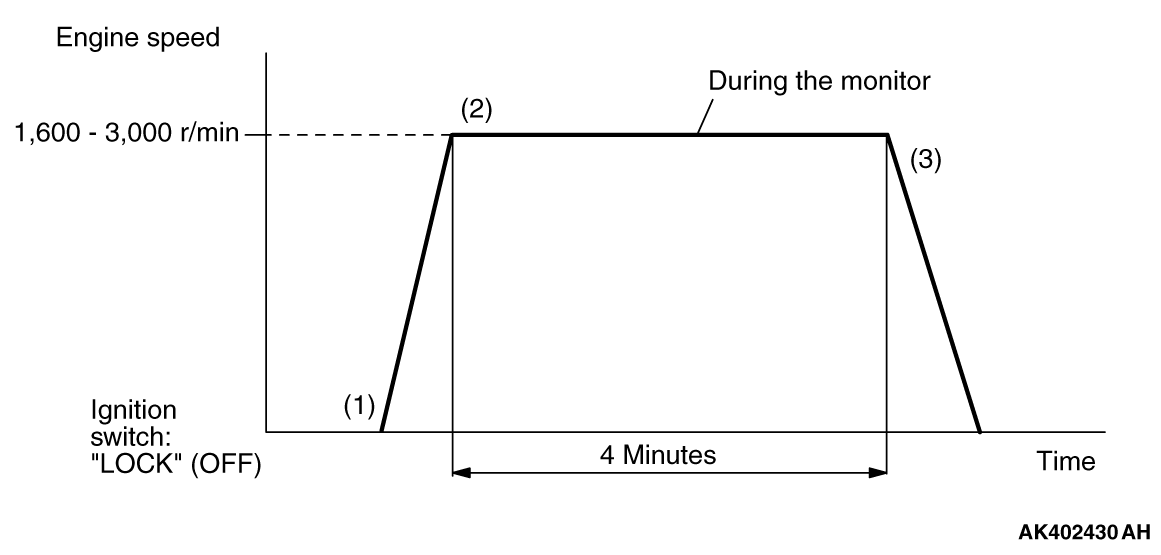
  1. Start the engine with all the accessories switched OFF.
  2. Drive the vehicle for 4 minutes at the following conditions. (During the monitor)
    note When the system is normal, the monitor is completed earlier.

    • Vehicle speed: More than 30 km/h (19 mph)
    • Engine speed: More than 1,600 r/min, less than 3,000 r/min
    • Engine load: More than 20 %, less than 60 %
    • Without rapid accelerator pedal movement
  3. Stop the vehicle in a safe place and turn the ignition switch to "LOCK" (OFF) position.
  4. Start the engine and do Steps 1 to 3 again.
    note When the vehicle is operating normally and the OBD-II Drive Cycle is carried out, the Readiness Codes will be set as "Complete" on the first drive cycle. The second drive cycle is required to set the Readiness Codes as "Complete" if a fault is detected during the first drive cycle.
  5. Confirm that the diagnostic trouble code (DTC) is not output.


PATTERN 2
Test procedure

  1. Start the engine with all the accessories switched OFF.
  2. Let the engine idle for 10 seconds. (During the monitor)
  3. Turn the ignition switch to the "LOCK" (OFF) position.
  4. Start the engine and do Steps 1 to 3 again.
    note When the vehicle is operating normally and the OBD-II Drive Cycle is carried out, the Readiness Codes will be set as "Complete" on the first drive cycle. The second drive cycle is required to set the Readiness Codes as "Complete" if a fault is detected during the first drive cycle.
  5. Confirm that the diagnostic trouble code (DTC) is not output.


PATTERN 3
Drive cycle pattern


Inspection conditions

  • Engine coolant temperature: More than 82°C (180°F)
  • Intake air temperature: More than 5°C (41°F)
  • Barometric pressure: More than 76 kPa (22.5 inHg)
  • Condition of CVT: Selector lever "D" range

Test procedure

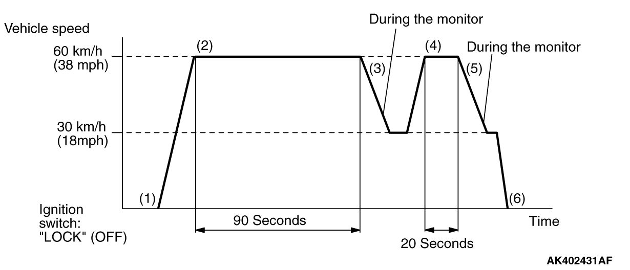
  1. Start the engine with all the accessories switched OFF.
  2. Accelerate until the vehicle speed is 60 km/h (38 mph) and then drive the vehicle for 90 seconds.
  3. Release the accelerator pedal and reduce vehicle speed to 30 km/h (18 mph). (During the monitor)
  4. Accelerate until the vehicle speed is 60 km/h (38 mph) and then drive the vehicle for 20 seconds.
  5. Release the accelerator pedal and reduce vehicle speed to 30 km/h (18 mph). (During the monitor)
  6. Stop the vehicle in a safe place and turn the ignition switch to "LOCK" (OFF) position.
  7. Start the engine and do Steps 1 to 6 again.
    note When the vehicle is operating normally and the OBD-II Drive Cycle is carried out, the Readiness Codes will be set as "Complete" on the first drive cycle. The second drive cycle is required to set the Readiness Codes as "Complete" if a fault is detected during the first drive cycle.
  8. Confirm that the diagnostic trouble code (DTC) is not output.


PATTERN 4
Drive cycle pattern


Inspection conditions

  • Engine coolant temperature: More than 30°C (86°F)
  • Intake air temperature: More than -10°C (14°F)
  • Barometric pressure: More than 76 kPa (22.5 inHg)
  • Condition of CVT: Selector lever "D" range

Test procedure

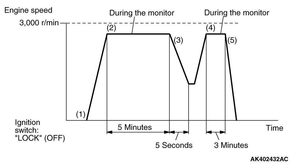
  1. Start the engine with all accessories switched OFF.
  2. Drive the vehicle for 5 minutes at the following conditions. (During the monitor)

    • Engine speed: Less than 3,000 r/min
    • Airflow rate: More than 13 g/sec, less than 45 g/sec
    • Accelerator pedal: Except full close
    • Without rapid accelerator pedal movement
  3. Release the accelerator pedal for 5 seconds.
  4. Drive the vehicle for 3 minutes at the following conditions. (During the monitor)

    • Engine speed: Less than 3,000 r/min
    • Airflow rate: More than 13 g/sec, less than 45 g/sec
    • Accelerator pedal: Except full close
    • Without rapid accelerator pedal movement
      note When the system is normal, the monitor is completed earlier.
  5. Stop the vehicle in a safe place and turn the ignition switch to "LOCK" (OFF) position.
  6. Start the engine and do Steps 1 to 5 again.
    note When the vehicle is operating normally and the OBD-II Drive Cycle is carried out, the Readiness Codes will be set as "Complete" on the first drive cycle. The second drive cycle is required to set the Readiness Codes as "Complete" if a fault is detected during the first drive cycle.
  7. Confirm that the diagnostic trouble code (DTC) is not output.


PATTERN 5
Drive cycle pattern


Inspection conditions

  • Engine coolant temperature at engine start: Less than 36°C (96°F)
  • Intake air temperature at engine start: Less than 36°C (96°F)
  • Fuel amount at engine start: More than 15 %, less than 40 %
  • Engine coolant temperature: More than 60°C (41°F)
  • Intake air temperature: More than 5°C (41°F)
  • Barometric pressure: More than 76 kPa (22.5 inHg)
  • Fuel temperature: Less than 36°C (96°F)
  • Condition of CVT: Selector lever "D" range

Test procedure

  1. Start the engine with all the accessories switched OFF.
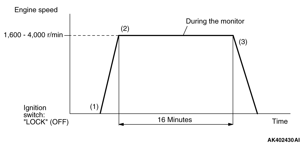
  2. Drive the vehicle for 16 minutes at the following conditions. (During the monitor)

    • Engine speed: More than 1,600 r/min, less than 4,000 r/min
    • Vehicle speed: More than 30 km/h (18.7 mph)
    • Engine load: More than 20 %, less than 70 %
    • Without rapid accelerator pedal movement
      note Keep running as long as possible with the power steering pressure switch in the OFF position.
      note When the system is normal, the monitor is completed earlier.
  3. Stop the vehicle in a safe place and turn the ignition switch to "LOCK" (OFF) position.
  4. Start the engine and do Steps 1 to 3 again.
    note When the vehicle is operating normally and the OBD-II Drive Cycle is carried out, the Readiness Codes will be set as "Complete" on the first drive cycle. The second drive cycle is required to set the Readiness Codes as "Complete" if a fault is detected during the first drive cycle.
  5. Confirm that the diagnostic trouble code (DTC) is not output.


PATTERN 6
Inspection conditions

  • Engine coolant temperature at engine start: Less than 36°C (96°F)
  • Intake air temperature at engine start: Less than 36°C (96°F)
  • Fuel amount at engine start: More than 40 %, less than 85 %
  • Engine coolant temperature: More than 20°C (68°F)
  • Intake air temperature: More than 5°C (41°F)
  • Barometric pressure: More than 76 kPa (22.5 inHg)
  • Fuel temperature: Less than 32°C (90°F)

Test procedure

  1. Start the engine with all the accessories switched OFF.
  2. Let the engine idle for 16 minutes. (During the monitor)
    note When the system is normal, the monitor is completed earlier.
  3. Turn the ignition switch to "LOCK" (OFF) position.
  4. Start the engine and do Steps 1 to 3 again.
    note When the vehicle is operating normally and the OBD-II Drive Cycle is carried out, the Readiness Codes will be set as "Complete" on the first drive cycle. The second drive cycle is required to set the Readiness Codes as "Complete" if a fault is detected during the first drive cycle.
  5. Confirm that the diagnostic trouble code (DTC) is not output.


PATTERN 7
Drive cycle pattern


Inspection conditions

  • Engine coolant temperature at engine start: More than 0°C (32°F)
  • Condition of CVT: Selector lever "D" range

Test procedure

  1. Start the engine with all the accessories switched OFF.
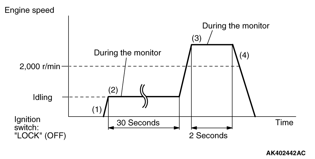
  2. Let the engine idle for 30 seconds. (During the monitor)
  3. Accelerate the vehicle for 2 seconds at the following conditions. (During the monitor)

    • Engine speed: More than 2,000 r/min
    • Engine load: More than 60 %
    • Throttle position sensor output voltage: More than 3.5 volts
  4. Stop the vehicle in a safe place and turn the ignition switch to "LOCK" (OFF) position.
  5. Start the engine and do Steps 1 to 4 again.
  6. Confirm that the diagnostic trouble code (DTC) is not output.


PATTERN 8
Drive cycle pattern


Inspection conditions

  • Engine coolant temperature: More than 76°C (169°F)
  • Condition of CVT: Selector lever "D" range

Test procedure

  1. Start the engine with all the accessories switched OFF.
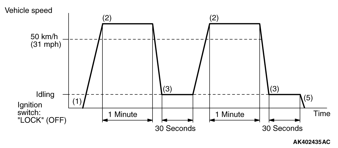
  2. Drive the vehicle at more than 50 km/h (31 mph) for 1 minute.
  3. Stop the vehicle in a safe place and let the engine idle for 30 seconds.
  4. Repeat Steps 2 and 3 again.
  5. Stop the vehicle in a safe place and turn the ignition switch to "LOCK" (OFF) position.
  6. Confirm that the diagnostic trouble code (DTC) is not output.


PATTERN 9
Drive cycle pattern


Inspection conditions

  • Engine coolant temperature at engine start: More than 7°C (47°F)
  • Intake air temperature: Less than 60°C (140°F)
  • Engine coolant temperature: More than 40°C (104°F)
  • Condition of CVT: Selector lever "D" range

Test procedure

  1. Start the engine with all the accessories switched OFF.
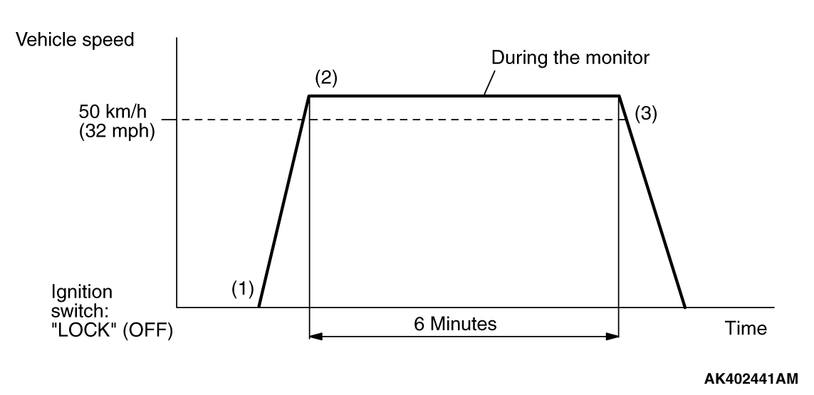
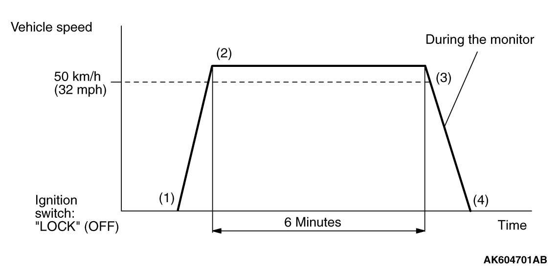
  2. Drive the vehicle for 6 minutes at the following condition. (During the monitor)

    • Vehicle speed: More than 50 km/h (32 mph)
    • Except fuel cut
  3. Stop the vehicle in a safe place and turn the ignition switch to "LOCK" (OFF) position.
  4. Confirm that the diagnostic trouble code (DTC) is not output.


PATTERN 10
Drive cycle pattern


Inspection conditions

  • Engine coolant temperature at engine start: More than 10°C (50°F), less than 76°C (168°F)
  • Intake air temperature at engine start: More than 10°C (14°F)
  • Dropping of intake air temperature since engine start: Less than 5°C (9°F)
  • Condition of CVT: Selector lever "D" range

Test procedure

  1. Start the engine with all the accessories switched OFF.
  2. Drive the vehicle for 20 minutes at the following conditions. (During the monitor)

    • Vehicle speed: More than 50 km/h (32 mph)
    • Except fuel cut
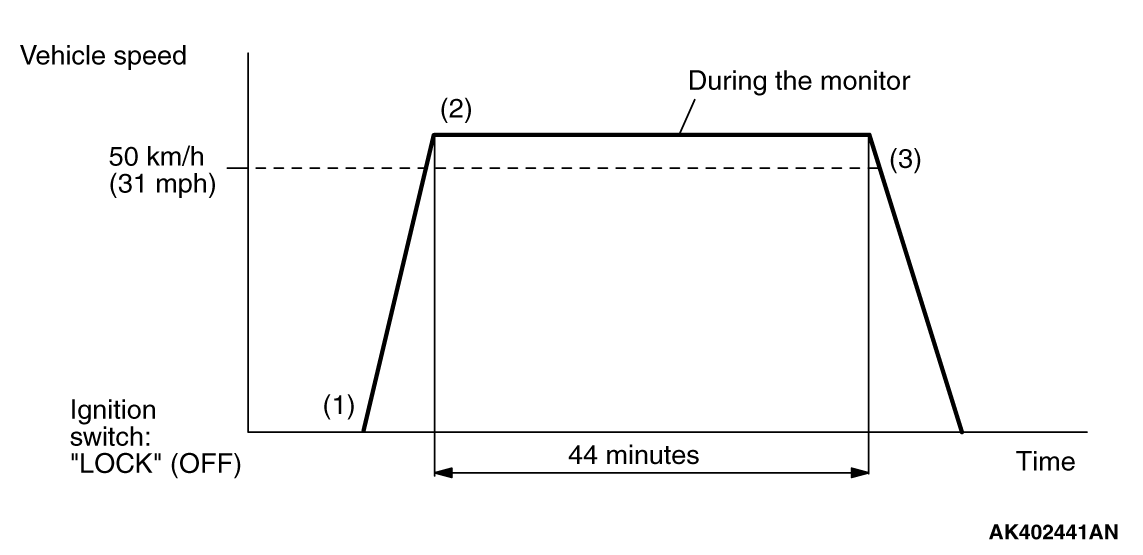
      note The system is normal if engine coolant temperature will rise more than 82°C (180°F) within 44 minutes.
  3. Stop the vehicle in a safe place and turn the ignition switch to "LOCK" (OFF) position.
  4. Start the engine and do Steps 1 to 3 again.
  5. Confirm that the diagnostic trouble code (DTC) is not output.


PATTERN 11
Drive cycle pattern


Inspection conditions

  • Engine coolant temperature: More than 76°C (169°F)
  • Condition of CVT: Selector lever "D" range

Test procedure

  1. Start the engine with all the accessories switched OFF.
  2. Drive the vehicle at 50 km/h (31 mph) for 6 minutes.
  3. Release the accelerator pedal for 10 seconds then stop the vehicle in a safe place. (During the monitor)
  4. Turn the ignition switch to "LOCK" (OFF) position.
  5. Start the engine and do Steps 1 to 4 again.
  6. Confirm that the diagnostic trouble code (DTC) is not output.


PATTERN 12
Drive cycle pattern


Inspection conditions

  • Engine coolant temperature: More than 82°C (180°F)
  • Condition of CVT: Selector lever "D" range

Test procedure

  1. Start the engine with all the accessories switched OFF.
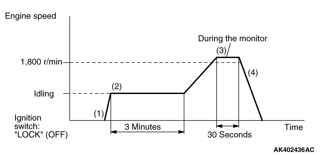
  2. Let the engine idle for 3 minutes.
  3. Drive the vehicle for 30 seconds at the following conditions. (During the monitor)

    • Engine speed: More than 1,800 r/min
    • Engine load: More than 30 %, less than 80 %
    • Throttle position sensor output: Less than 3.0 volts
    • Except fuel cut
  4. Stop the vehicle in a safe place and turn the ignition switch to "LOCK" (OFF) position.
  5. Confirm that the diagnostic trouble code (DTC) is not output.


PATTERN 13
Drive cycle pattern


Inspection conditions

  • Engine coolant temperature: More than 76°C (169°F)
  • Condition of CVT: Selector lever "D" range

Test procedure

  1. Start the engine with all the accessories switched OFF.
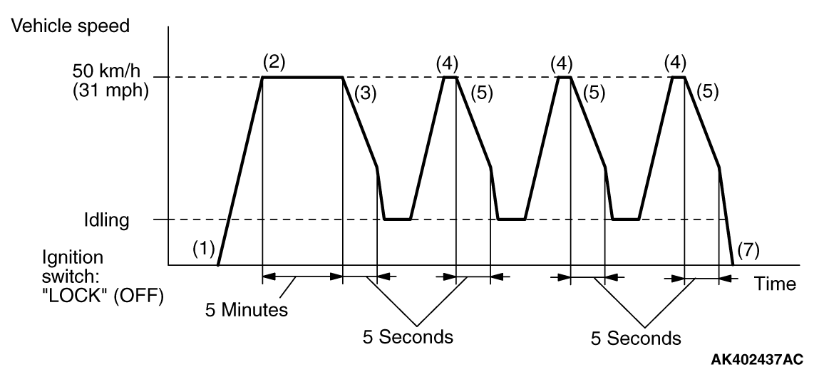
  2. Drive the vehicle at 50 km/h (31 mph) for 5 minutes.
  3. Release the accelerator pedal for 5 seconds then stop the safe place.
  4. Accelerate until the vehicle speed is at 50 km/h (31 mph) at the following conditions.

    • Engine speed: More than 1,500 r/min
    • Engine load: More than 40 %
  5. Release the accelerator pedal for 5 seconds then stop the safe place.
  6. Repeat Steps 4 and 5 for 2 times.
  7. Stop the vehicle in a safe place and turn the ignition switch to "LOCK" (OFF) position.
  8. Start the engine and do Steps 1 to 7 again.
  9. Confirm that the diagnostic trouble code (DTC) is not output.


PATTERN 14
Inspection conditions

  • Engine coolant temperature at engine start: More than -10°C (14°F), less than 33°C (91°F)
  • Difference between engine coolant temperature and intake air temperature at engine start: Less than 5°C (9°F)
  • Condition of CVT: Selector lever "D" range

Test procedure

  1. Start the engine with all the accessories switched OFF.
  2. Drive the vehicle at more than 30 km/h (19 mph) until engine coolant temperature rises more than 60°C (140°F). (During the monitor)
  3. Stop the vehicle in a safe place and turn the ignition switch to "LOCK" (OFF) position.
  4. Start the engine and do Steps 1 to 3 again.
  5. Confirm that the diagnostic trouble code (DTC) is not output.


PATTERN 15
Drive cycle pattern


Inspection conditions

  • Engine coolant temperature: More than -10°C (14°F)
  • Intake air temperature: More than -10°C (14°F)
  • Barometric pressure: More than 76 kPa (22.5 inHg)
  • Condition of CVT: Selector lever "D" range

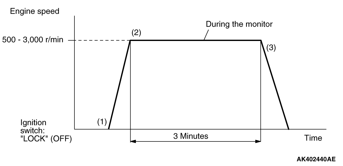
Test procedure

  1. Start the engine with all the accessories switched OFF.
  2. Drive the vehicle for 3 minutes at the following conditions. (During the monitor)

    • Engine speed: More than 500 r/min, less than 3,000 r/min
    • Engine load: More than 25 %
    • Without rapid accelerator pedal change
    • Except fuel cut
  3. Stop the vehicle in a safe place and turn the ignition switch to "LOCK" (OFF) position.
  4. Start the engine and do Steps 1 to 3 again.
  5. Confirm that the diagnostic trouble code (DTC) is not output.


Drive cycle pattern


Inspection condition
Condition of CVT: Selector lever "D" range
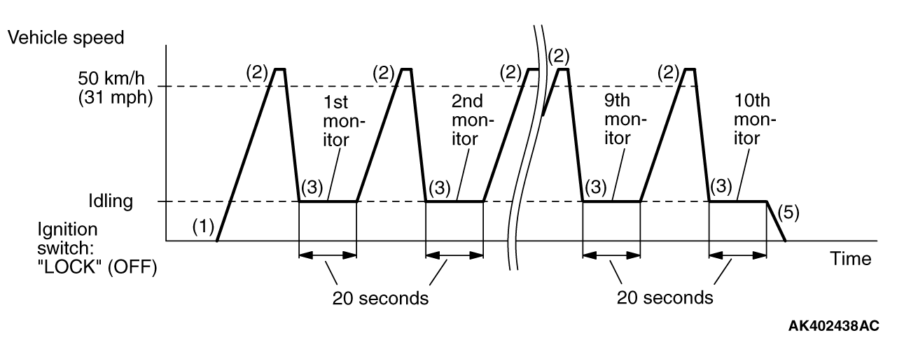
Test procedure

  1. Start the engine with all the accessories switched OFF.
  2. Accelerate until the vehicle speed is more than 50 km/h (31 mph).

    • Engine speed: More than 2,500 r/min
    • Engine load: More than 55 %
  3. Stop the vehicle in a safe place and let the engine idle for 20 seconds. (During the monitor)
  4. Repeat Steps 2 and 3 for 10 times.
  5. Stop the vehicle in a safe place and turn the ignition switch to "LOCK" (OFF) position.
  6. Start the engine and do Steps 1 to 5 again.
  7. Confirm that the diagnostic trouble code (DTC) is not output.


PATTERN 17
Drive cycle pattern


Inspection conditions

  • Engine coolant temperature: More than 30°C (86°F)
  • Condition of CVT: Selector lever "D" range

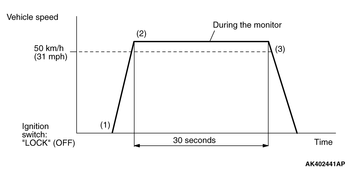
Test procedure

  1. Start the engine with all the accessories switched OFF.
  2. Drive the vehicle at more than 50 km/h (31 mph) for 30 seconds. (During the monitor)
  3. Stop the vehicle in a safe place and turn the ignition switch to "LOCK" (OFF) position.
  4. Start the engine and do Steps 1 to 3 again.
  5. Confirm that the diagnostic trouble code (DTC) is not output.


PATTERN 18
Inspection conditions

  • Engine coolant temperature: More than 82°C (180°F)
  • Intake air temperature: More than -10°C (14°F)
  • Barometric pressure: More than 76 kPa (22.5 inHg)
  • Condition of CVT: Selector lever "D" range

Test procedure

  1. Start the engine with all the accessories switched OFF.
  2. Accelerate until the vehicle speed is more than 1.5 km/h (1 mph).
  3. Stop the vehicle in a safe place and let the engine idle for 1 minute. (During the monitor)
  4. Turn the ignition switch to "LOCK" (OFF) position.
  5. Start the engine and do Steps 1 to 4 again.
  6. Confirm that the diagnostic trouble code (DTC) is not output.


PATTERN 19
Inspection conditions

  • Engine coolant temperature: More than 7°C (45°F), less than 40°C (104°F)
  • Intake air temperature: More than -10°C (14°F)
  • Barometric pressure: More than 76 kPa (22.5 inHg)

Test procedure

  1. Start the engine with all the accessories switched OFF.
  2. Let the engine idle for 1 minute. (During the monitor)
  3. Turn the ignition switch to "LOCK" (OFF) position.
  4. Start the engine and do Steps 1 to 3 again.
  5. Confirm that the diagnostic trouble code (DTC) is not output.


PATTERN 20
Inspection conditions

  • Engine coolant temperature: More than 77°C (171°F), less than 87°C (189°F)
  • Barometric pressure: More than 76 kPa (22.5 inHg)

Test procedure

  1. Start the engine with all the accessories switched OFF.
  2. Drive the engine at 1,200 - 1,500 r/min for 30 seconds. (During the monitor)
  3. Turn the ignition switch to "LOCK" (OFF) position.
  4. Start the engine and do Steps 1 to 3 again.
  5. Confirm that the diagnostic trouble code (DTC) is not output.


PATTERN 21
Inspection condition
Engine coolant temperature: More than 82°C (180°F)
Test procedure

  1. Start the engine with all the accessories switched OFF.
  2. Let the engine idle for 15 minutes. (During the monitor)
  3. Turn the ignition switch to "LOCK" (OFF) position.
  4. Start the engine and do Steps 1 to 3 again.
  5. Confirm that the diagnostic trouble code (DTC) is not output.


PATTERN 22
Inspection conditions

  • Intake air temperature: More than -10°C (14°F)
  • Engine coolant temperature sensor: More than 7°C (45°F)

Test procedure

  1. Start the engine with all the accessories switched OFF.
  2. Let the engine idle for 4 minutes. (During the monitor)
  3. Turn the ignition switch to "LOCK" (OFF) position.
  4. Start the engine and do Steps 1 to 3 again.
  5. Confirm that the diagnostic trouble code (DTC) is not output.


PATTERN 23
Inspection conditions

  • Fuel temperature sensor: Less than 36°C (96°F) <Fuel tank pressure sensor monitor>
  • Fuel amount at engine start: Less than 85 % <Fuel tank pressure sensor monitor>

Test procedure

  1. Start the engine with all the accessories switched OFF.
  2. Let the engine idle at the engine speed less than 1,000 r/min for 15 seconds. (During the monitor)
  3. Turn the ignition switch to "LOCK" (OFF) position.
  4. Confirm that the diagnostic trouble code (DTC) is not output.


SYSTEM READINESS TEST STATUS


PURPOSE


The Readiness function (also referred to as I/M Readiness or I/M Flags) indicates if a full diagnostic check has been "Completed" (is "Ready") for each non-continuous monitor. Enhanced I/M State Emission Programs will use the Readiness status (Codes) to see if the vehicle is ready for OBD-II testing. "Incomplete" (Not Ready) codes will be one of the triggers for I/M failure.

OVERVIEW


The ECM monitors the following main diagnosis items and records whether the evaluation was completed or is incomplete. The Readiness Codes are established for the I/M programs, thereby confirming that the vehicles have not been tampered with by erasing the diagnostic trouble code(s) (DTCs) before I/M testing. The Readiness Codes and DTCs can be reset by disconnecting the battery or by erasing the codes with a scan tool MB991958 (M.U.T.-III sub assembly). For this reason, all the Readiness Codes must be displayed "Complete" before I/M testing.
When the monitors run and complete, the scan tool MB991958 (M.U.T.-III sub assembly) will display the Readiness Codes as "Complete" (General Scan Tools display as "Ready"). When the vehicle is operating normally and the OBD-II Drive Cycle is carried out, the Readiness Codes will be set as "Complete" on the first drive cycle. For DTCs requiring two drive cycles to detect a fault, the second drive cycle is required to set the Readiness Codes as "Complete" if a fault is detected during the first drive cycle. If the fault is still there after the second drive cycle, a DTC will be set.

After all the Readiness Codes are displayed as "Complete", the technician is assured that any DTCs related to the monitor will be displayed if the system has a problem. That is why some State’s I/M programs require the Readiness Code as "Complete" before they check for DTCs.
note After a repair is made for a DTC, the technician should drive the OBD-II Drive Cycle checking that the scan tool MB991958 (M.U.T.-III Sub Assembly) displays all the Readiness Codes as "Complete".