DTC P0791: Malfunction of Secondary Pulley Speed Sensor
DIAGNOSTIC FUNCTION
The TCM determines whether the system is faulty by monitoring the secondary pulley speed sensor.
DESCRIPTIONS OF MONITOR METHODS
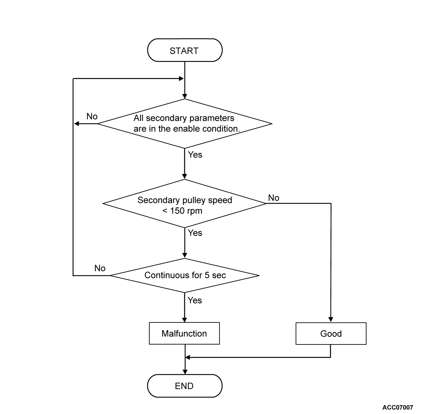
- The status with the primary pulley speed of 1,000 r/min or more and with the secondary pulley speed of 150 r/min or less continues for five seconds.
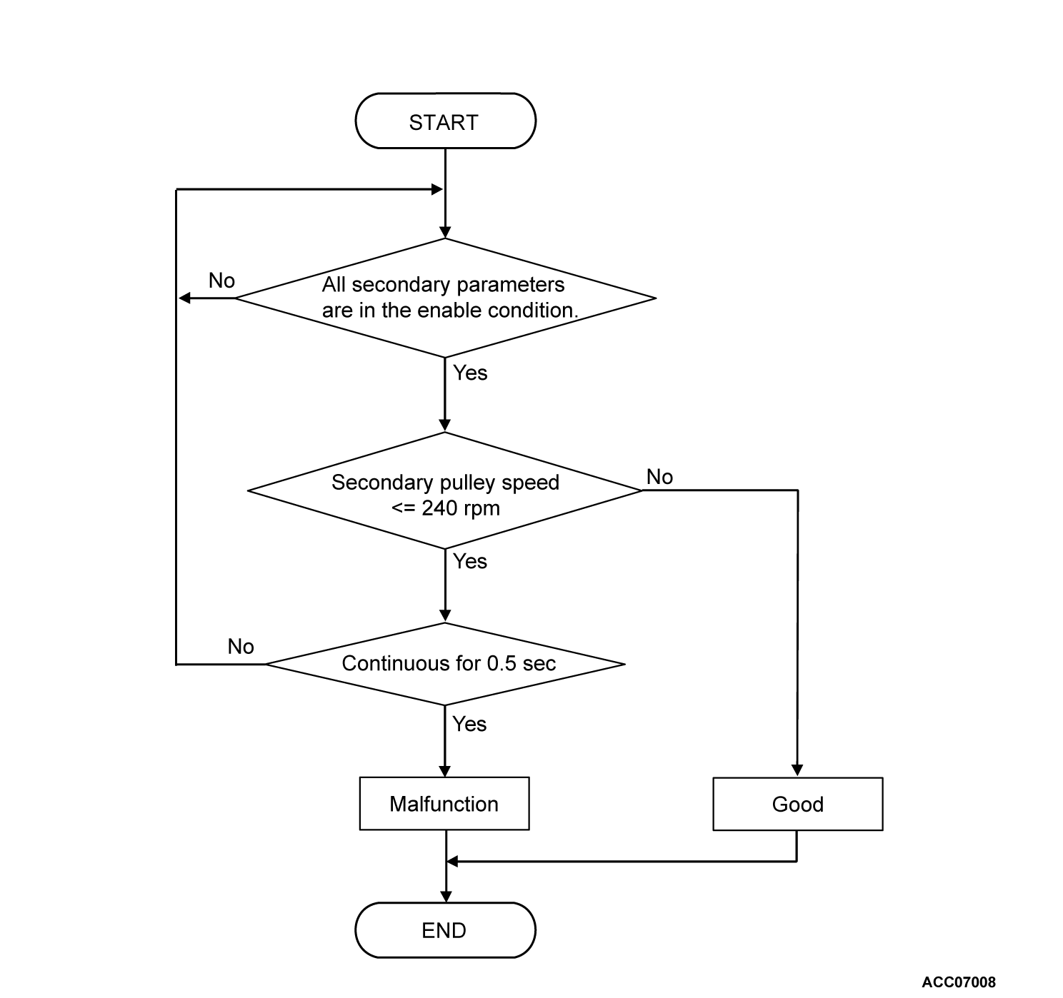
- When the secondary pulley speed has dropped abruptly from 1,000 r/min or more to 240 r/min or less, and then it keeps 240 r/min or less for 0.5 second continuously.
MONITOR EXECUTION
Continuous
MONITOR EXECUTION CONDITIONS (OTHER MONITOR AND SENSOR)
Other Monitor (There is no temporary DTC stored in memory for the item monitored below)
- P0715: Malfunction of the primary pulley speed sensor
Sensor (The sensor below is determined to be normal)
- Primary pulley speed sensor
DTC SET CONDITIONS
Check Conditions
- Voltage of battery: 10 volts or more
- Voltage of battery: 16.5 volts or less
Judgment Criteria
- The status with the primary pulley speed of 1,000 r/min or more and with the secondary pulley speed of less than 150 r/min continues for five seconds.
- The secondary pulley speed has dropped abruptly from 1,000 r/min or more to 240 r/min or less. Then at least 0.5 second have passed with the reduced speed.
OBD-II DRIVE CYCLE PATTERN
The vehicle is driven for at least 10 seconds with the engine speed at 1,500 r/min or more.
PROBABLE CAUSES
- Malfunction of secondary pulley speed sensor
- Damaged wiring harness and connectors
- Malfunction of TCM
DIAGNOSIS
Required Special Tools:
- MB992744: Vehicle communication interface-Lite (V.C.I.-Lite)
- MB992745: V.C.I.-Lite main harness A
- MB992747: V.C.I.-Lite USB cable short
- MB992748: V.C.I.-Lite USB cable long
- MB991958: Scan Tool (M.U.T.-III Sub Assembly)
- MB991824: Vehicles Communication Interface (V.C.I.)
- MB991827: M.U.T.-III USB Cable
- MB991910: M.U.T.-III Main Harness A (Vehicles with CAN communication system)
STEP 1. Check the following connector.
- Secondary pulley speed sensor connector
Check the terminals for a contact status problem and internal short circuit.
Is the check result normal?
 Repair the faulty connector.
STEP 2. Check for open circuit in SGN2 line between the secondary pulley speed sensor connector and the TCM connector.
STEP 3. Voltage measurement at secondary pulley speed sensor connector (terminal number 1).
(1) Disconnect the secondary pulley speed sensor connector, and measure at the wiring harness side.
(2) Turn the ignition switch to the "ON" position.
(3) Measure the voltage between the secondary pulley speed sensor connector (terminal number 1) and body ground.
OK: 10 volts or more
Is the check result normal?
 Repair the connector(s) or the wiring harness (power supply line between the secondary pulley speed sensor connector terminal number 1 and the J/B connector).
STEP 4. Check the following connector.
- TCM connector
Check the terminals for a contact status problem and internal short circuit.
Is the check result normal?
 Repair the faulty connector.
STEP 5. Check for open circuit or short to ground in SECS line between the secondary pulley speed sensor connector and the TCM connector.
STEP 6. Measure the output wave pattern of the secondary pulley speed sensor at TCM connector (SECS terminal).
(1) Connect the secondary pulley speed sensor connector and TCM connector.
(3) Transmission range: "D" range
(4) Drive at a constant speed of approximately 20 km/h (12.4 mph).
(5) Use an oscilloscope, measure the voltage between TCM connector SECS terminal and body ground.
Is the check result normal?
STEP 7. Using scan tool (M.U.T.-III), recheck the DTC.
Check again if the DTC is stored.
(1) Erase the DTC.
(2) Turn the ignition switch to the "LOCK" (OFF) position.
(3) Carry out a test drive with the OBD-II drive cycle pattern.
(4) Recheck the DTC.
Is DTC P0791 stored?
![[Previous]](../../../buttons/fprev.png)
![[Next]](../../../buttons/fnext.png)


