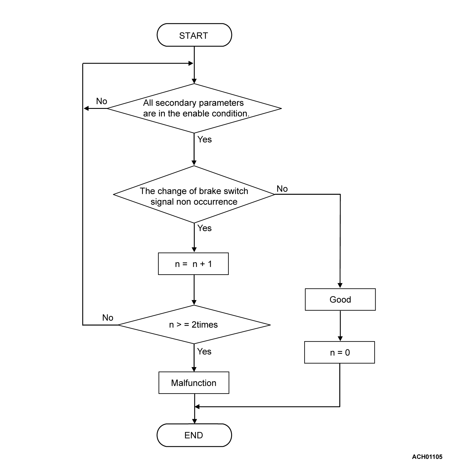
DTC P0703: Malfunction of Brake Switch
DIAGNOSTIC FUNCTION
TCM detects malfunction using the stoplight switch signal sent from the ETACS-ECU.
DESCRIPTIONS OF MONITOR METHODS
Drive the vehicle at 30 km/h (19 mph) or more for 10 seconds, and then stop the vehicle more for 10 seconds. In this sequential operation, no variation has been found in the stoplight switch input signal in two consecutive times.
MONITOR EXECUTION
Continuous
MONITOR EXECUTION CONDITIONS (OTHER MONITOR AND SENSOR)
Other Monitor (There is no temporary DTC stored in memory for the item monitored below)
- U0141: CAN time-out error (ETACS)
Sensor (The sensor below is determined to be normal)
- Not applicable
DTC SET CONDITIONS
Check Conditions
- Voltage of battery: 10 volts or more
- Voltage of battery: 16.5 volts or less
- Go/Stop operation of CVT: done
- Go operation: Drive the vehicle at 30 km/h (19 mph) or more for 10 seconds
- Stop operation: Stop the vehicle more for 10 seconds
Judgment Criteria
- TCM detected no change in stoplight switch signal during Go/Stop operation twice.
OBD-II DRIVE CYCLE PATTERN
Perform the following pattern twice:
- The vehicle is driven for at least 10 seconds at 60 km/h (37.3 mph) or more while the selector lever is at "D" position. then vehicle is stopped for at least 20 seconds while the selector lever is at "P" position
PROBABLE CAUSES
- Malfunction of the CAN bus
- Malfunction of the stoplight switch
- Damaged wiring harness and connectors
- Malfunction of TCM
- Malfunction of ETACS-ECU
DIAGNOSIS
Required Special Tools:
- MB992744: Vehicle communication interface-Lite (V.C.I.-Lite)
- MB992745: V.C.I.-Lite main harness A
- MB992747: V.C.I.-Lite USB cable short
- MB992748: V.C.I.-Lite USB cable long
- MB991958: Scan Tool (M.U.T.-III Sub Assembly)
- MB991824: Vehicles Communication Interface (V.C.I.)
- MB991827: M.U.T.-III USB Cable
- MB991910: M.U.T.-III Main Harness A (Vehicles with CAN communication system)
| caution |
|
STEP 1. Using scan tool (M.U.T.-III), diagnose the CAN bus lines.
| caution | To prevent damage to scan tool (M.U.T.-III), always turn the ignition switch to the "LOCK" (OFF) position before connecting or disconnecting scan tool (M.U.T.-III). |
Using scan tool (M.U.T.-III), perform CAN bus diagnosis [Refer to GROUP 54C, Explanation About The Scan Tool (M.U.T.-III) Can Bus Diagnostics  ].
].
 ].
].Is the check result normal?
STEP 2. Using scan tool (M.U.T.-III), recheck the DTC after repairing CAN bus lines.
Check again if the DTC is stored. This diagnosis is complete.
(1) Erase the DTC.
(2) Turn the ignition switch to the "LOCK" (OFF) position.
(3) Carry out a test drive with the OBD-II drive cycle pattern.
(4) Recheck the DTC.
Is DTC P0703 stored?
 This diagnosis is complete.
STEP 3. Check the stoplight and the high-mounted stoplight for proper function.
Check the stoplight and the high-mounted stoplight for proper operation when the brake pedal is depressed. Check that the stoplight illuminates when the brake pedal is depressed and that it goes out when the brake pedal is released.
OK:
- When the brake pedal is depressed: Illuminates
- When the brake pedal is released: goes out
Is the check result normal?
STEP 4. Check for stoplight switch installation.
Refer to GROUP 35A, On-vehicle Service - Brake Pedal Check and Adjustment  .
.
 .
.Is the check result normal?
STEP 5. Check the stoplight switch continuity.
STEP 6. Voltage measurement at the ETACS-ECU connector.
(1) Connector check: ETACS-ECU connector, stoplight switch connector
(2) Turn the ignition switch to the "ON" position.
(3) Measure the voltage between the stoplight switch terminal and body ground.
OK:
- When the brake pedal is released: 1 volt or less
- When the brake pedal is depressed: approximately 5 volts or more
Is the check result normal?
STEP 7. Using scan tool (M.U.T.-III), recheck the DTC.
Check again if the DTC is stored.
(1) Erase the DTC.
(2) Turn the ignition switch to the "LOCK" (OFF) position.
(3) Carry out a test drive with the OBD-II drive cycle pattern.
(4) Recheck the DTC.
Is DTC P0703 stored?
STEP 8. Using scan tool (M.U.T.-III), recheck the DTC.
Check again if the DTC is stored. This diagnosis is complete.
(1) Erase the DTC.
(2) Turn the ignition switch to the "LOCK" (OFF) position.
(3) Carry out a test drive with the OBD-II drive cycle pattern.
(4) Recheck the DTC.
Is DTC P0703 stored?
 This diagnosis is complete.
![[Previous]](../../../buttons/fprev.png)
![[Next]](../../../buttons/fnext.png)

