DISASSEMBLY AND ASSEMBLY
|
Required Special Tools:
- MD998773: Knock Sensor Wrench
- MD998245: Installer Lock Pin
DISASSEMBLY SERVICE POINTS
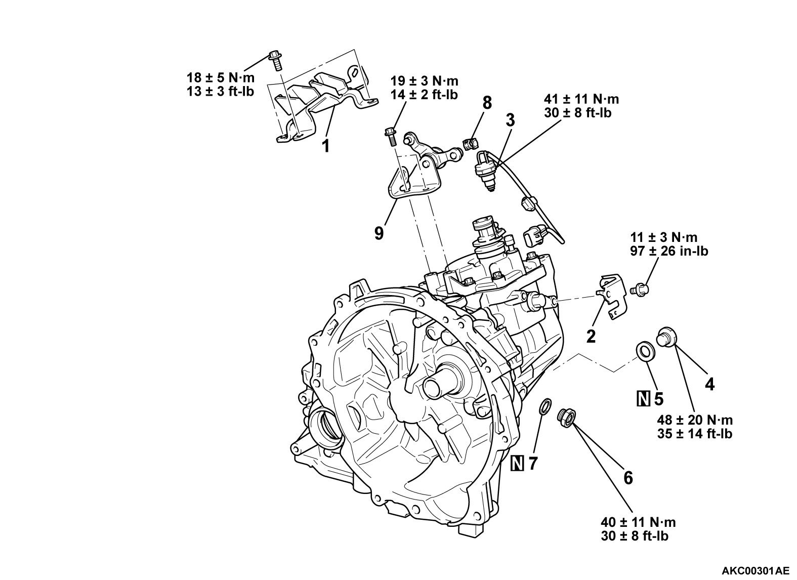
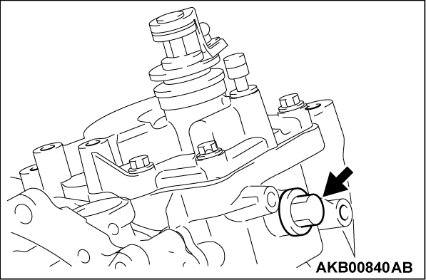
<<A>> BACK-UP LIGHT SWITCH REMOVAL
Using the special tool MD998773, remove the back-up light switch from the transaxle case assembly.
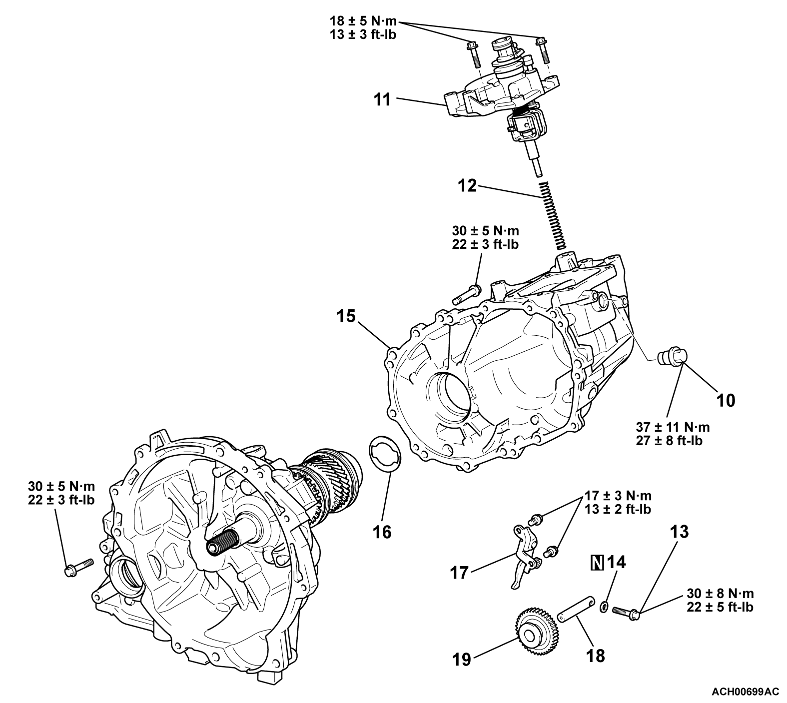
<<D>> TRANSAXLE CASE ASSEMBLY REMOVAL
1. Using the tire-lever large remove the transaxle case assembly.
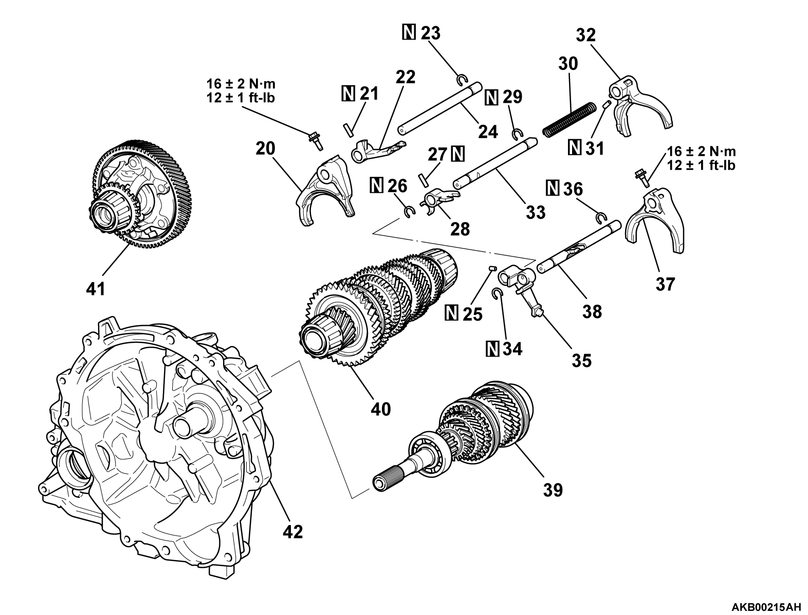
<<E>> GEAR SHIFT FORK NUMBER 1/INPUT SHAFT ASSEMBLY/OUTPUT SHAFT ASSEMBLY REMOVAL
Remove the gear shift fork number 1, input shaft assembly and output shaft assembly together.
ADJUSTMENT BEFORE ASSEMBLY
SELECTING THE INPUT SHAFT RADIAL BALL BEARING AXIAL PLAY ADJUSTMENT SHIM
1. Set the input shaft assembly to the clutch housing assembly.
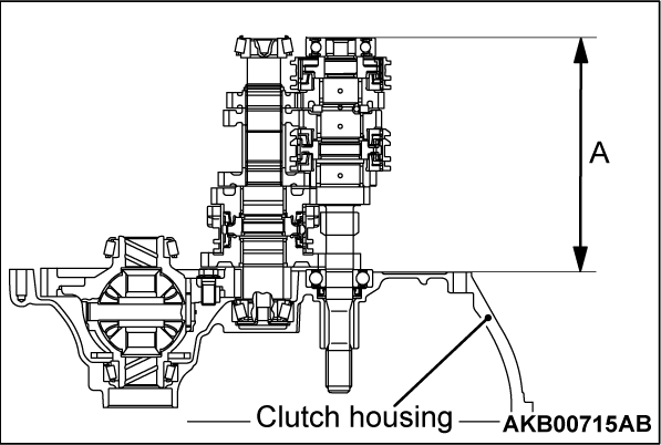
2. Put the clutch housing assembly on the surface table and measure the dimension "A" which is from the mating surface of the clutch housing assembly to the end surface of the bearing outer race, with a height gauge.
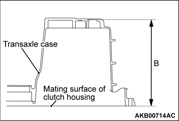
3. Put the straight edge on the mating surface of the transaxle case assembly and measure the dimension "B" with a vernier caliper.
4. Calculate thickness "C" of the required shim by the following formula. Select a shim which most closely matches this thickness.
With in 0 to 0.1 mm (0 to 0.004 inch) = "B" - "A" - "C"
ASSEMBLY SERVICE POINTS
>>A<< OUTPUT SHAFT ASSEMBLY/INPUT SHAFT ASSEMBLY INSTALLATION
Install the input shaft assembly and output shafts assembly together.
>>B<< STRAIGHT PIN/SLOTTED SPRING PIN INSTALLATION
1. Align the pin holes in the shift rail and shift fork.
2. Using the installer lock pin special tool (MD998245) insert the new slotted pin and slotted spring pin.
>>C<< REVERSE IDLER GEAR SUB-ASSEMBLY/REVERSE IDLER GEAR SHAFT INSTALLATION
1. Install the reverse idler gear sub-assembly and reverse idler gear shaft to the clutch housing assembly.
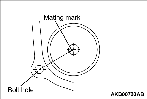
2. Before installing the transaxle case assembly, confirm that the reverse idler gear addition mark is positioned as show in the illustration.
>>D<< SHIM (INPUT SHAFT RADIAL BALL BEARING AXIAL PLAY ADJUSTMENT) INSTALLATION
Install the shim selected in "ADJUSTMENT BEFORE REASSEMBLY" to the input shaft installation surface of the transaxle case assembly.
>>E<< TRANSAXLE CASE ASSEMBLY INSTALLATION
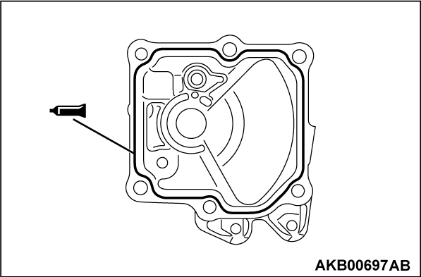
| caution | Squeeze sealant evenly onto the transaxle case assembly. Do not leave gaps or excess amounts, otherwise oil leaks are likely. |
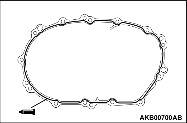
1. Apply a 1.2 mm (0.05 inch) diameter bead of specified sealant as illustrated onto the transaxle case assembly.
Specified sealant: MITSUBISHI GENUINE PART Number MZ100388 or equivalent
| note | Be sure to install the transaxle case assembly onto the clutch housing case while the sealant is still wet (within 10 minutes). |
2. Tighten the transaxle case mounting bolts to the specified torque.
Tightening torque: 30 ± 5 N·m (22 ± 3 ft-lb).
| note | After installation, keep the sealed area away from the oil for approximately one hour. |
>>F<< FLANGE BOLT INSTALLATION
Using screwdriver [8 mm (0.3 inch) in shank diameter], align the flange bolt installation holes of transaxle case and reverse idler gear shaft and tighten the flange bolt to the specified torque.
Tightening torque: 30 ± 8 N·m (22 ± 5 ft-lb).
>>G<< SHIFT AND SELECT LEVER SHAFT ASSEMBLY INSTALLATION
| caution | Squeeze sealant onto the case. Do not leave gaps or excess amounts, otherwise oil leaks are likely. |
1. Apply a 1.2 mm (0.05 inch) diameter bead of sealant as illustrated onto the control shaft cover of the shift and select lever shaft assembly.
Specified sealant: MITSUBISHI GENUINE PART Number MZ100388 or equivalent
| note | Be sure to install the shift and select lever shaft assembly to the transaxle case quickly while the sealant is still wet (within 10 minutes). |
2. Install the shift and select lever shaft assembly to the transaxle case assembly and tighten the bolts to specified torque.
Tightening torque: 18 ± 3 N·m (13 ± 23 ft-lb)
| note | After installation, keep the sealed area away from the oil for approximately one hour. |
![[Previous]](../../../buttons/fprev.png)
![[Next]](../../../buttons/fnext.png)
