REMOVAL AND INSTALLATION
| caution | Never overhaul the V.V.T. sprocket assembly. |
Required Special Tool:
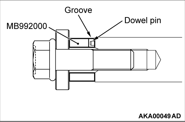
- MB992000: Crankshaft Adapter
REMOVAL SERVICE POINTS
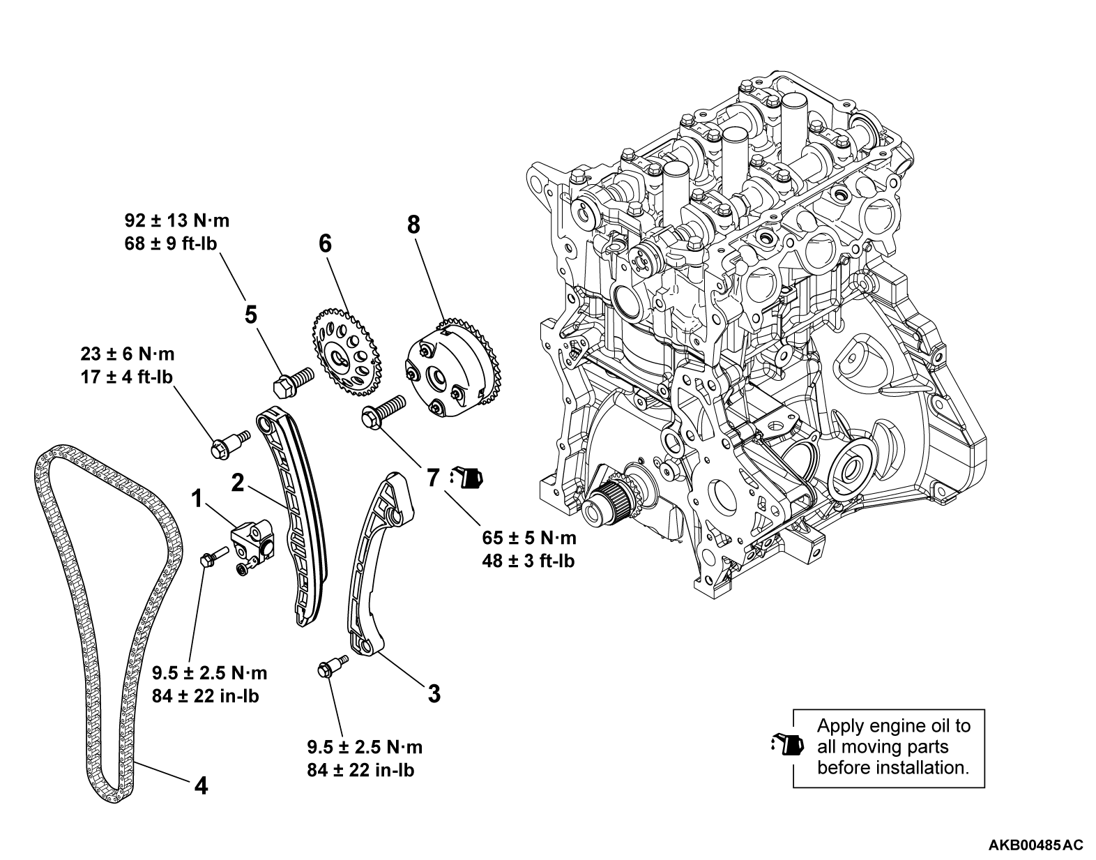
<<A>> TIMING CHAIN TENSIONER REMOVAL
1. Set the special tool MB992000 to the crankshaft, and install the crankshaft pulley center bolt and washer.
2.
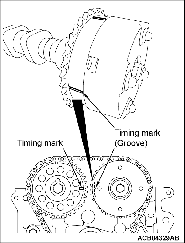
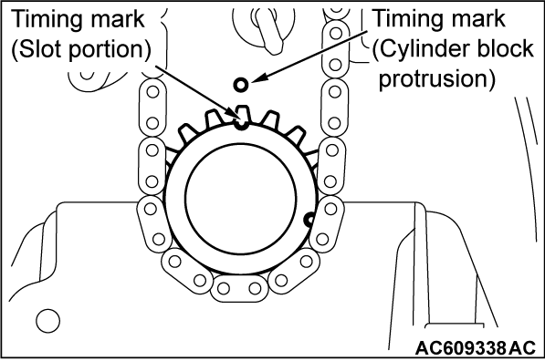
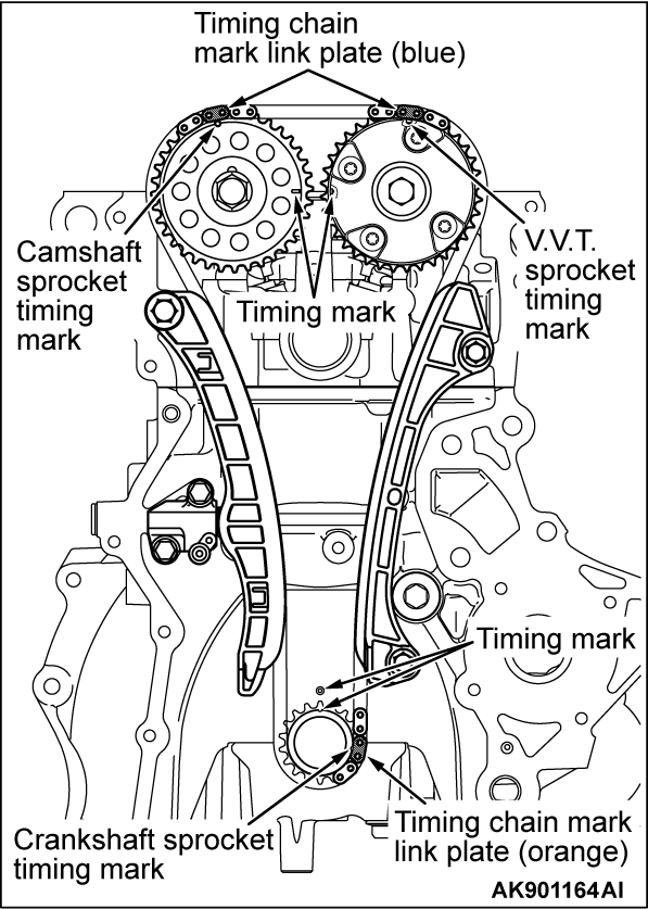
Turn the crankshaft clockwise, and align the timing marks of the sprocket. Then set number 1 cylinder to the top dead center (TDC).
| caution | Never turn the crankshaft counterclockwise. |
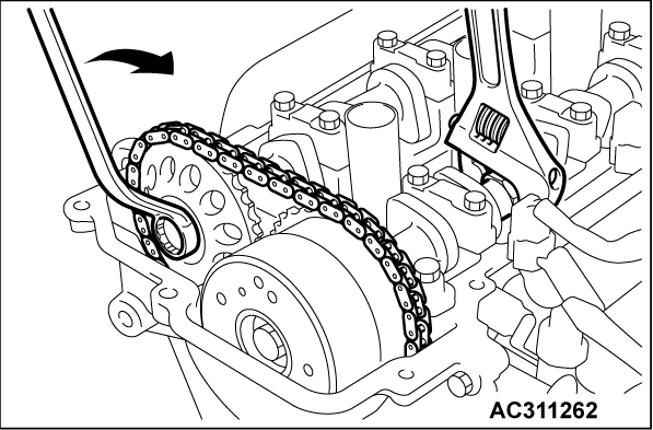
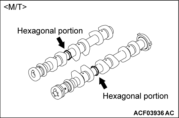
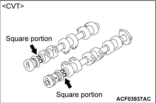
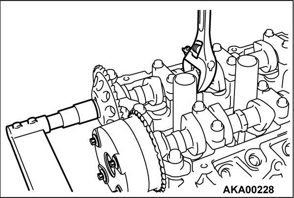
3. While holding the intake camshaft hexagonal portion <M/T> or square portion <CVT> with a wrench or a similar tool, slightly turn the exhaust camshaft clockwise to tighten the timing chain at the timing chain tensioner side and shorten the plunger of the timing chain tensioner.
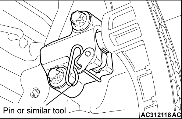
4. With the plunger of the tensioner shortened, insert a pin [3 mm (0.1 inch) in diameter] or a similar tool to the hole shown in the illustration of the timing chain tensioner.
| note | Pull out the pin or a similar tool after installing the timing chain tensioner. |
5.
| caution | Do not turn the crankshaft after removing the timing chain tensioner. |
Remove the timing chain tensioner.
<<B>> CAMSHAFT SPROCKET BOLT REMOVAL
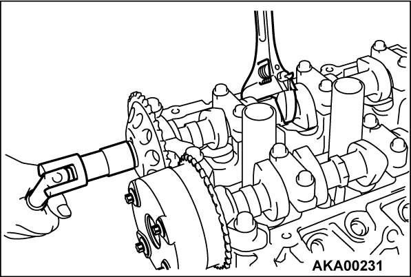
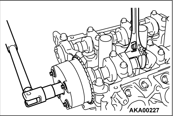
While holding the hexagonal portion <M/T> or square portion <CVT> of the camshaft with a wrench, remove the camshaft sprocket bolt.
<<C>> V.V.T. SPROCKET BOLT REMOVAL
While holding the hexagonal portion <M/T> or square portion <CVT> of the camshaft with a wrench, remove the V.V.T. sprocket bolt.
INSTALLATION SERVICE POINTS
>>A<< V.V.T. SPROCKET BOLT INSTALLATION
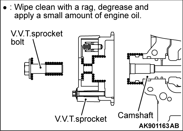
1. Apply a proper minimum quantity of engine oil to the following points.
- Camshaft end
- Insertion hole in V.V.T. sprocket (all over inside and outside surfaces)
- Threads and head of V.V.T. sprocket bolt
- Bearing surface of V.V.T. sprocket bolt
2. Install the V.V.T. sprocket onto the camshaft.
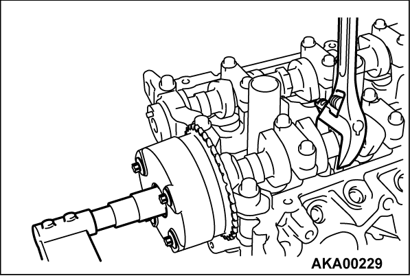
3. Make sure that the V.V.T. sprocket is installed all the way onto the camshaft. Holding the hexagonal portion <M/T> or square portion <CVT> of the camshaft with a wrench, check that the V.V.T. sprocket does not turn.
4. While holding the hexagonal portion <M/T> or square portion <CVT> of the camshaft with a wrench, tighten the V.V.T. sprocket bolt to the specified torque.
Tightening torque: 65 ± 5 N·m (48 ± 3 ft-lb)
>>B<< CAMSHAFT SPROCKET BOLT INSTALLATION
While holding the hexagonal portion <M/T> or square portion <CVT> of the camshaft with a wrench, tighten the V.V.T. sprocket bolt to the specified torque.
Tightening torque: 92 ± 13 N·m (68 ± 9 ft-lb)
>>C<< TIMING CHAIN INSTALLATION
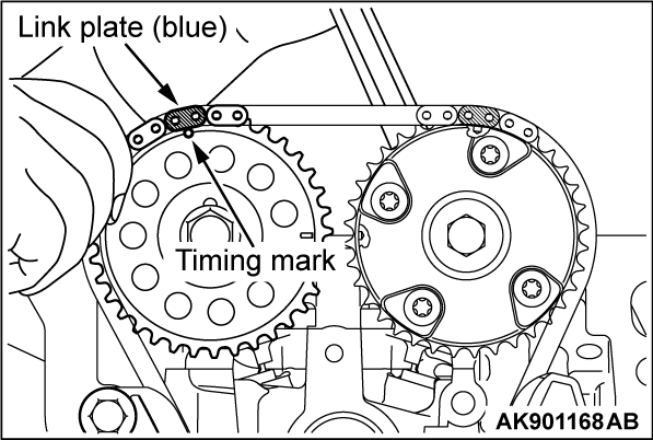
1. Set the two mark link plates (blue) of the three timing chain mark link plates to the camshaft sprocket and V. V. T. sprocket side, and set the other mark link plate (orange) to the crankshaft side.
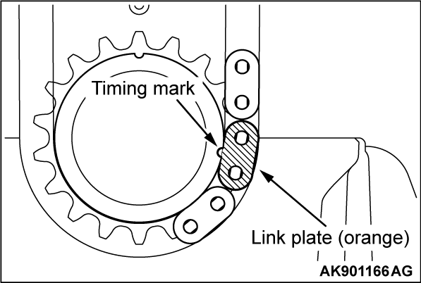
2. Install the timing chain onto the crankshaft sprocket, aligning the mark link plate (orange) with the mark on the sprocket.
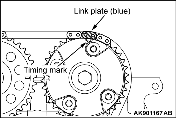
3. Install the chain onto the V.V.T. sprocket, aligning the mark link plate (blue) with the mark on the sprocket.
4. Install the chain onto the camshaft sprocket, aligning the mark link plate (blue) with the mark on the sprocket. When doing this, rotate the V.V.T. sprocket or the camshaft sprocket by a tooth or two and then align the mark link plate (blue) and the timing mark.
5. Ensure that all of the three pairs of the timing marks are aligned.
6. Install the chain guide and the tensioner lever.
>>D<< TIMING CHAIN TENSIONER INSTALLATION
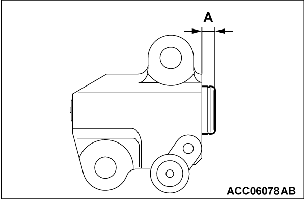
1. Check the projection (A) of the timing chain tensioner plunger.
2. If the plunger projection does not satisfy the standard value [approximately 4 mm (0.2 inch)], observe the following procedure to adjust it.
(1) Pull the pin or the similar tool out of the tensioner.
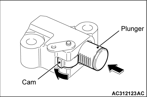
(2) Rotate the tensioner cam in the arrow direction to push the plunger slowly.
(3) Insert the pin or the similar tool again when the plunger projection reaches approximately 4 mm (0.2 inch).
(4) Check that the projection of the locked plunger is approximately 4 mm (0.2 inch).
3. Install the timing chain tensioner with the pin or the similar tool to the cylinder block, and tighten the timing chain tensioner mounting bolts to the specified torque.
Tightening torque: 9.5 ± 2.5 N·m (84 ± 22 in-lb)
4. After installing the timing chain tensioner, confirm that the timing marks of each sprocket are aligned with the TDC of number 1 cylinder, and the marked link plate (blue-colored area) of the timing chain is aligned with the specified position of each sprocket. Then pull out the pin or a similar tool of the timing chain tensioner, and apply tension to the timing chain.
5. Remove the crankshaft adapter special tool (MB992000).
![[Previous]](../../../buttons/fprev.png)
![[Next]](../../../buttons/fnext.png)
