TROUBLESHOOTING CONTENTS
| danger | The SRS-ECU adopts the rollover specification that the curtain airbag and seat belt pre-tensioner operate at the occurrence of rollover. Therefore, do not tilt the vehicle to the right and left with the IG ON or tilt the SRS-ECU to the right and left with the IG ON and the harness installed. |
| caution | During diagnosis, a diagnostic trouble code (DTC) associated with other system may be set when the ignition switch is turned "ON" with connector(s) disconnected. On completion, confirm all systems for DTC(s). If DTC(s) are set, erase them all. |
| warning | Since the radiator fan rotates during CAN bus line diagnostics, make sure that no one is servicing the engine compartment before diagnosing the CAN bus line. Since the CAN communication stops when diagnosing the CAN bus line, the ETACS-ECU detects the time-out of the engine control module, and activates the radiator fan to prevent overheating as fail-safe. |
Troubleshooting of electronic control systems for which the scan tool (M.U.T.-III) can be used follows the basic outline described below. Even in systems for which the scan tool (M.U.T.-III) cannot be used, part of these systems still follow this outline.
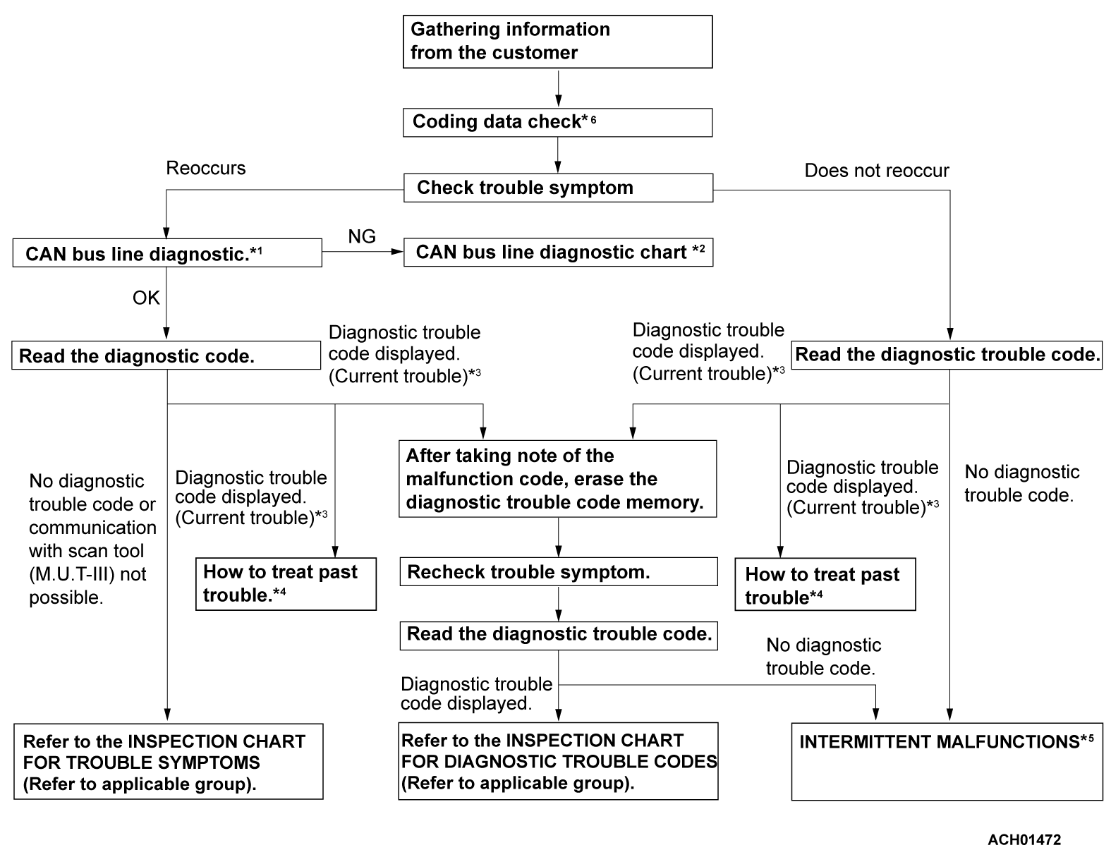
1. STANDARD FLOW OF DIAGNOSTIC TROUBLESHOOTING
Troubleshooting sections are based on the diagnostic flow as below. If the diagnostic flow is different from that given below, or if additional explanation is required, the details of such differences or additions will also be listed.
- *1: For how to diagnostic CAN bus lines, refer to GROUP 54C
 .
. - *2: For the CAN bus diagnostic chart, refer to GROUP 54C
 .
. - *3: When scan tool (M.U.T.-III) detects a diagnostic trouble code, its display informs users whether a mechanical symptom currently exists or whether it existed before. The message for the former state identifies it as an "Active" and the message for the latter identifies it as a "Stored".
- *4: For how to treat past trouble, refer to
 .
. - *5: For how to cope with intermittent malfunctions, refer to
 .
. - *6: For coding data, refer to
 .
.
2. SYSTEM OPERATION AND SYMPTOM VERIFICATION TESTS
If verification of the symptom(s) is difficult, procedures for checking operation and verifying symptoms are shown.
3. DIAGNOSTIC FUNCTION
The following trouble code diagnosis are shown.
- How to read DTC
- How to erase DTC
- Data list output
- Actuator test
4. DIAGNOSTIC TROUBLE CODE CHART
If the scan tool (M.U.T.-III) displays a DTC, find the applicable inspection procedure according to this chart.
5. SYMPTOM CHART
If there are symptoms, even though the scan tool (M.U.T.-III) show that no DTCs are stored, inspection procedures for each symptom will be found by using this chart.
6. DIAGNOSTIC TROUBLE CODE PROCEDURES
7. SYMPTOM PROCEDURES
8. DATA LIST REFERENCE TABLE
Inspection items and normal judgment values have been provided in this chart as reference information.
9. ACTUATOR TEST TABLE
The actuator test item numbers, inspection items, and judgment values have been provided in this chart as reference information.
10. CHECK AT ECU TERMINALS
Terminal numbers for the ECU connectors, inspection items, and standard values have been provided in this chart as reference information.
TERMINAL VOLTAGE CHECKS
1. Connect a needle-nosed wire probe to a voltmeter probe.
| caution | Short-circuiting the positive (+) probe between a connector terminal and ground could damage the vehicle wiring, the sensor, the ECU, or all three. Use care to prevent this! |
2. Insert the needle-nosed wire probe into each of the ECU connector terminals from the wire side, and measure the voltage while referring to the check chart.
| note | Measure voltage with the ECU connectors connected. You may find it convenient to pull out the ECU to make it easier to reach the connector terminals. Checks don't have to be carried out in the order given in the chart. |
3. If voltage readings differ from normal condition values, check related sensors, actuators, and wiring. Replace or repair as needed.
4. After repair or replacement, recheck with the voltmeter to confirm that the repair has corrected the problem.
TERMINAL RESISTANCE AND CONTINUITY CHECKS
1. Turn the ignition switch to the "LOCK" (OFF) position.
2. Disconnect the ECU connector.
| caution | If resistance and continuity checks are performed on the wrong terminals, damage to the vehicle wiring, sensors, ECU, and/or ohmmeter may occur. Use care to prevent this! |
3. Measure the resistance and check for continuity between the terminals of the ECU harness-side connector while referring to the check chart.
| note | Checks don't have to be carried out in the order given in the chart. |
4. If the ohmmeter shows any deviation from the normal condition value, check the corresponding sensor, actuator and related electrical wiring, then repair or replace.
5. After repair or replacement, recheck with the ohmmeter to confirm that the repair has corrected the problem.
11. INSPECTION PROCEDURES USING AN OSCILLOSCOPE
When there are inspection procedures using an oscilloscope, these are listed.
![[Previous]](../../../buttons/fprev.png)
![[Next]](../../../buttons/fnext.png)
