REMOVAL AND INSTALLATION <SNAP IN TYPE>
| warning | Certain components of this vehicle, such as TPMS sensors may contain perchlorate materials. Before deployment and/or disposal of these components, review and comply with all applicable Federal, state and local regulations. |
| caution |
|
Pre-removal Operation
|
REMOVAL SERVICE POINT
<<A>> TPMS TRANSMITTER REMOVAL
| caution | Be careful not to damage the TPMS transmitter. |
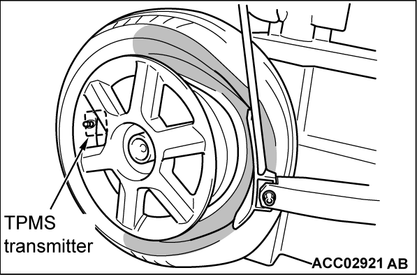
1. Fix the tire on a tire changing machine. Then apply a bead breaking shoe to the shown range to disengage the tire bead from the wheel rim.
| note | For the opposite side, repeat the same procedure. |
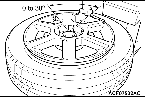
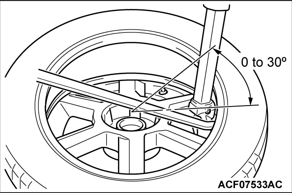
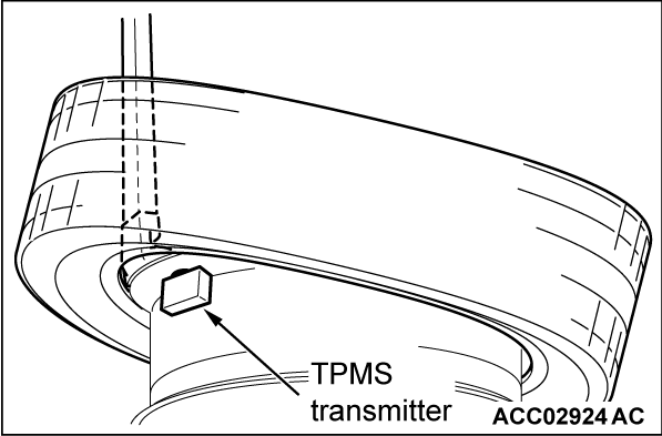
2. Fix the tire on a tire changing machine so that the TPMS transmitter is positioned as shown.
3.
Use a tire lever to disengage the upper bead.
| caution | Do not allow any impact or shock to the TPMS transmitter with a tire lever or tire bead. |
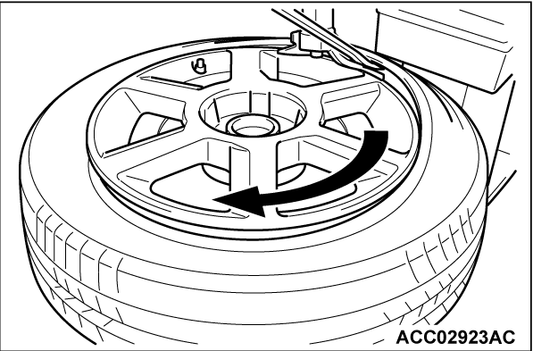
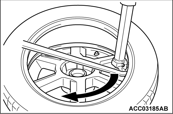
4. Rotate the tire in the direction of arrow to disengage the tire bead from the wheel.
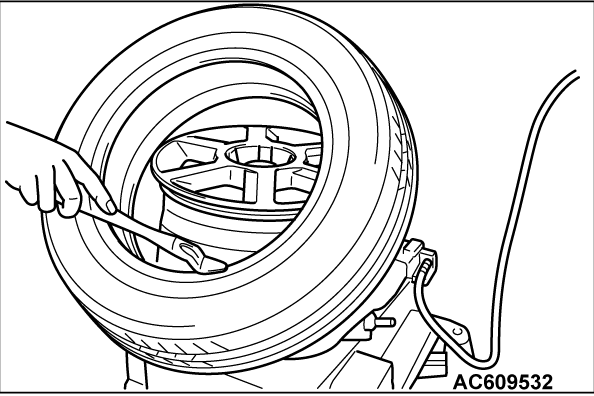
5. Fix the tire on a tire changing machine so that the TPMS transmitter is positioned as shown.
6.
Use a tire lever to disengage the lower bead.
| caution | Do not allow any impact or shock to the TPMS transmitter with a tire lever or tire bead. |
7. Rotate the tire in the direction of arrow to disengage the tire bead from the wheel.
8.
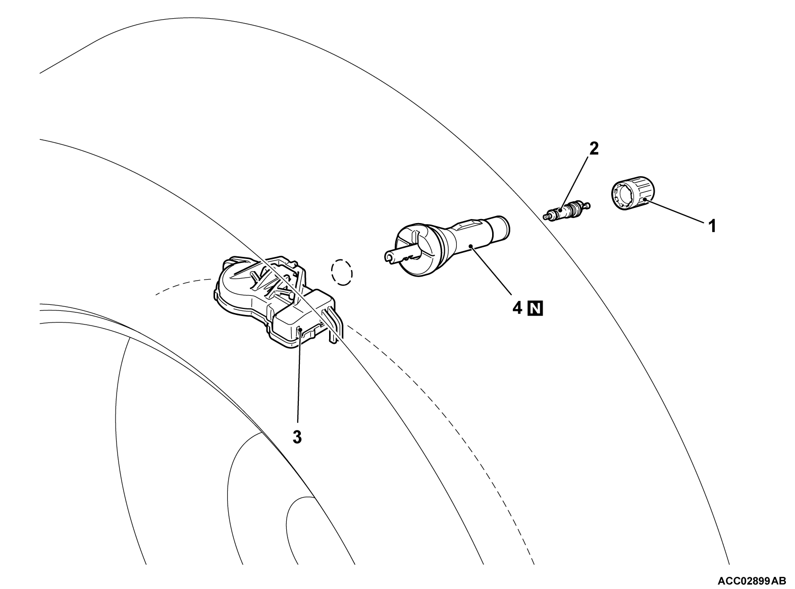
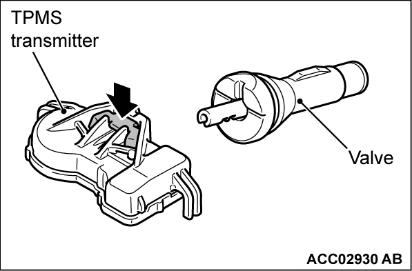
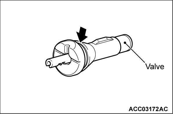
Remove the TPMS transmitter from the valve while depressing the portion indicated by the arrow.
| caution | Do not attempt to remove the TPMS transmitter without depressing the portion indicated by the arrow. |
9. Cut down the entire groove shown by the arrow to remove the valve.
INSTALLATION SERVICE POINTS
>>A<< VALVE INSTALLATION
1.
The projection shown by the arrow should face towards the outside of the wheel.
| caution | Install only the valve to wheel at first. |
>>B<< TPMS TRANSMITTER INSTALLATION
1.
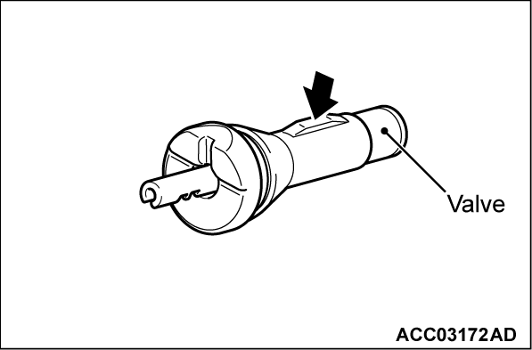
Install the TPMS transmitter into the valve while depressing the portion indicated by the arrow.
| caution | Do not attempt to install the TPMS transmitter without depressing the portion indicated by the arrow. |
2.
| caution | Make sure that the TPMS transmitter and the valve are installed securely. |
Pull the TPMS transmitter from the valve by hand to make sure it is secure.
| note | If the TPMS transmitter is disconnected from the valve, the tab securing the TPMS transmitter to the valve may be broken. |
>>C<< TIRE BEAD MOUNTING
1. Prepare the tire and fix the rim as usual.
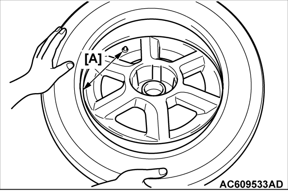
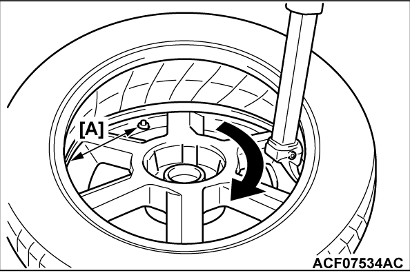
2. Put the tire on the rim, so that the cross point of the bead with the rim is approximately 20 cm (7.9 inch) [A] away from the valve.
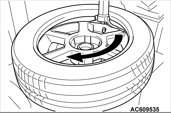
3. Engage the shoe and make sure that 20 cm (7.9 inch) [A] is maintained between the cross point and the valve.The arrow shows the direction of rotation of the wheel.
4. Turn the wheel in order to engage all the first side of the tire.
| note | The standard shoes can pass over the sensor without damaging it. |
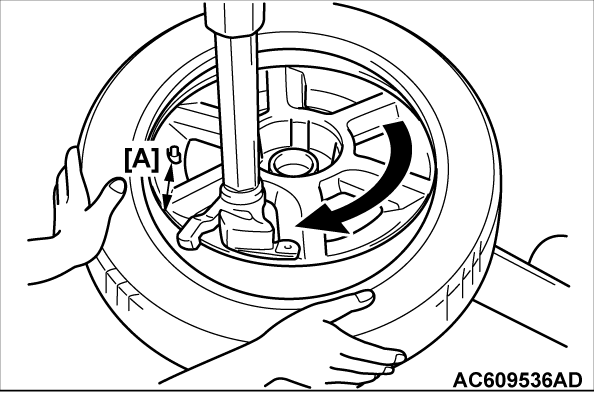
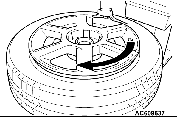
5. Put the second side of the tire in position, so that the cross point of the bead with the rim is approximately 20 cm (7.9 inch) [A] away from the valve. The curved arrow shows the direction of rotation of the wheel.
6. Turn the wheel in order to engage all of the second side of the tire.
| note | The standard shoes can pass over the sensor without damaging it. |
![[Previous]](../../../buttons/fprev.png)
![[Next]](../../../buttons/fnext.png)

