DTC U0001: Malfunction of CAN Communication Circuit
DIAGNOSTIC FUNCTION
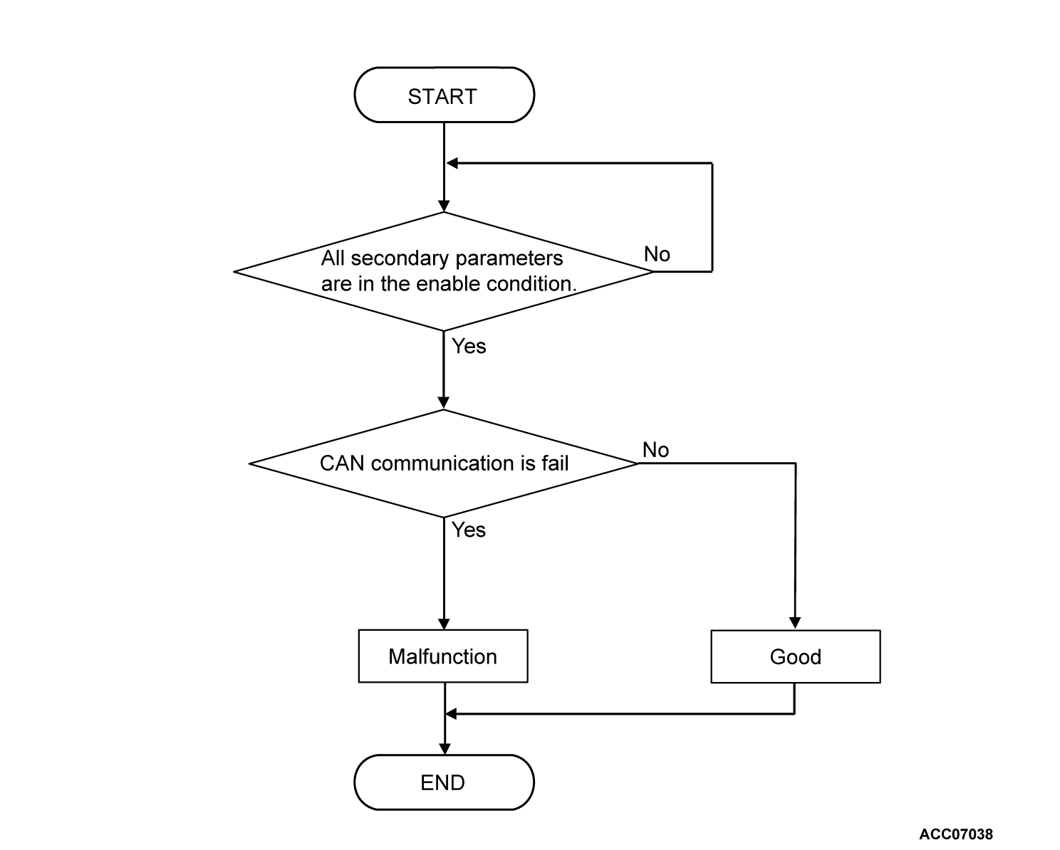
The TCM determines that the system is defective if CAN communication information cannot be sent or received.
DESCRIPTIONS OF MONITOR METHODS
- TCM cannot receive the periodic communication data.
MONITOR EXECUTION
- Continuous
MONITOR EXECUTION CONDITIONS (OTHER MONITOR AND SENSOR)
Other Monitor (There is no temporary DTC stored in memory for the item monitored below)
- Not applicable
Sensor (The sensor below is determined to be normal)
- Not applicable
DTC SET CONDITIONS
Check Conditions
- Time after TCM start: more than 0.7 seconds.
- Voltage of battery: 10 volts or more
- Voltage of battery: 16.5 volts or less
Judgment Criteria
- CAN communication: fail (Bus-off error is detected)
OBD-II DRIVE CYCLE PATTERN
Ignition switch: "ON" position (start the engine and keep it for 10 seconds or more)
PROBABLE CAUSES
- Malfunction of the CAN bus line
DIAGNOSIS
STEP 1. M.U.T.-III CAN bus diagnostics
Use M.U.T.-III to perform the CAN bus diagnosis.
Is the check result normal?
![[Previous]](../../../buttons/fprev.png)
![[Next]](../../../buttons/fnext.png)


