REMOVAL AND INSTALLATION
<M/T> |
REMOVAL SERVICE POINTS
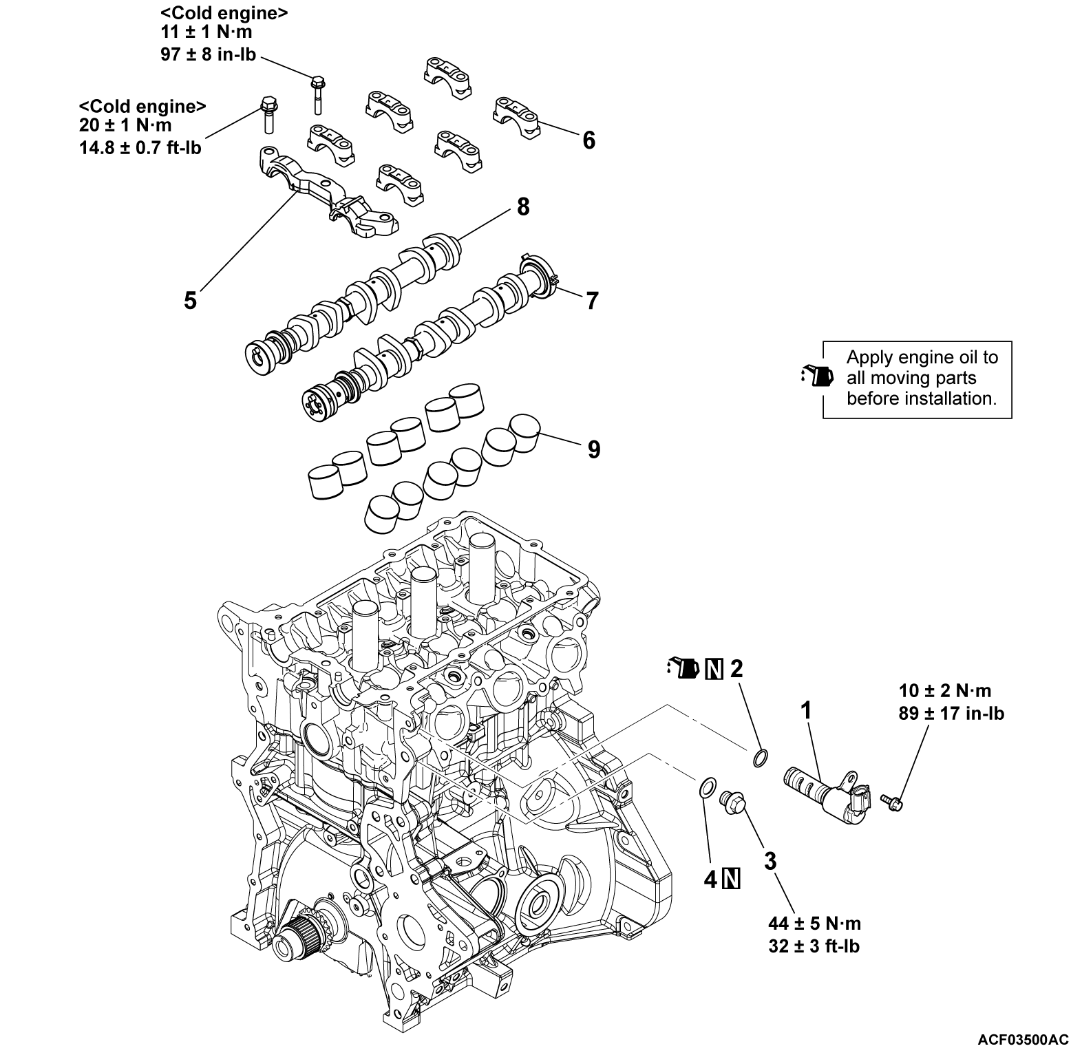
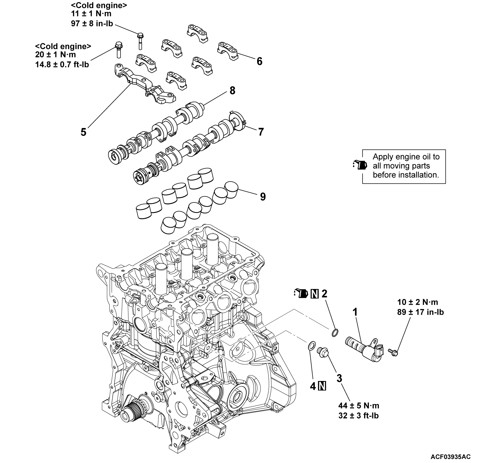
<<A>> CAMSHAFT BEARING CAP REMOVAL
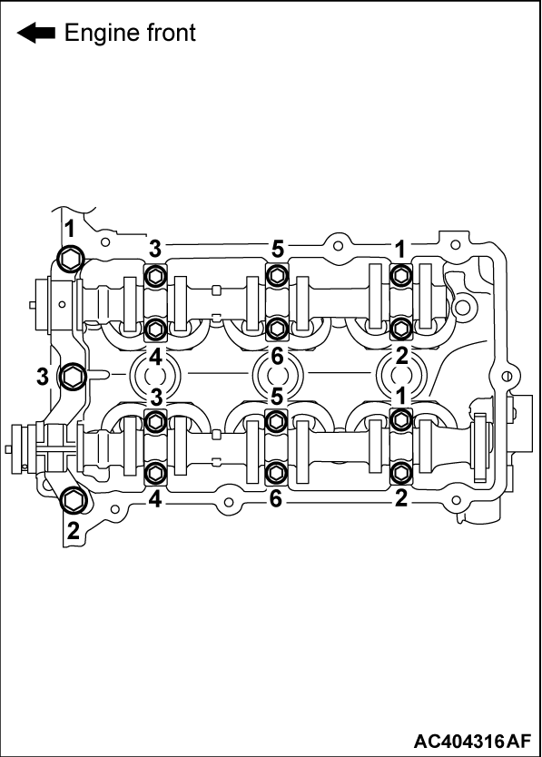
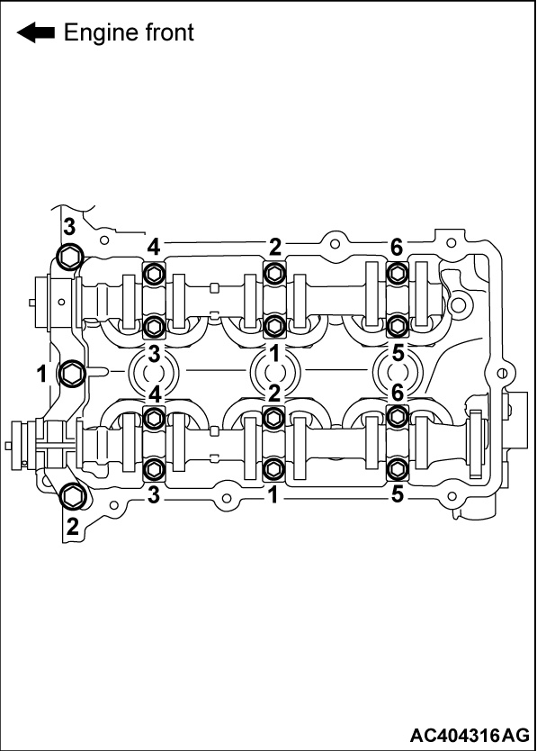
Loosen the front camshaft bearing cap mounting bolts, and then loosen each camshaft bearing cap mounting bolts in the order shown. Remove the front camshaft bearing cap and each camshaft bearing cap.
<<B>> VALVE TAPPET REMOVAL
To facilitate reassembly, attach a tag to each valve tappet removed that shows where it has been assembled.
INSTALLATION SERVICE POINTS
>>A<< VALVE TAPPET INSTALLATION
Reassemble each valve tappet to the correct location shown on the tag.
>>B<< EXHAUST CAMSHAFT/INTAKE CAMSHAFT/CAMSHAFT BEARING CAP/FRONT CAMSHAFT BEARING CAP INSTALLATION
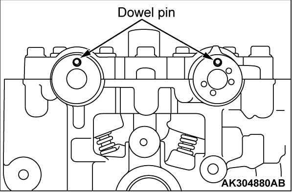
1. Install each camshaft, ensuring that the dowel pin faces the illustrated direction.
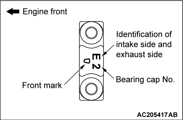
2. Camshaft bearing caps (number 2 to 4) are identical. To avoid confusion (bearing cap number and intake/exhaust side), confirm each identification mark and face the front mark towards the direction shown before installing them.
Identification mark (engraved on the front and bearing caps number 2 to 4)
- I: Intake side
- E: Exhaust side
3. Tighten each camshaft bearing cap mounting bolts to the specified torque in the order shown, and then tighten the front camshaft bearing cap mounting bolts as well.
Tightening torque:
- Camshaft bearing cap mounting bolts: 11 ± 1 N·m (97 ± 8 in-lb)
- Front camshaft bearing cap mounting bolts: 20 ± 1 N·m (14.8 ± 0.7 ft-lb)
>>C<< O-RING/OIL FEEDER CONTROL VALVE INSTALLATION
1.
| caution |
|
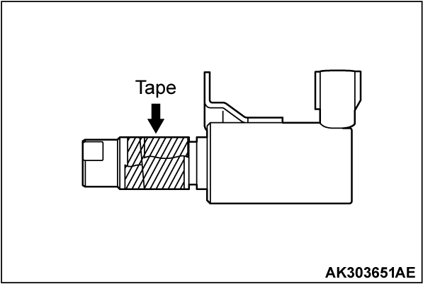
Apply a little amount of engine oil to the O-ring of oil feeder control valve.
2. Install the oil feeder control valve to the cylinder head.
3. Tighten the oil feeder control valve to the specified torque.
Tightening torque: 10 ± 2 N·m (89 ± 17 in-lb)
![[Previous]](../../../buttons/fprev.png)
![[Next]](../../../buttons/fnext.png)
